C
ONNECT
STC
S
TO
A
MPS
/M
OTOR
/E
NCODER
4-13
L
C
, 1
0
4
C
o
n
n
ec
tio
n
s t
o
S
te
p
M
o
to
rs
Connections to Step Motors
Open-Loop Step Motors
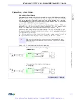
The controllers can control step motors in both open-loop (no encoder) and closed-loop con-
figurations. In the open-loop configuration, the step pulse output (connected to the drive) is fed
back into the line receivers and used to keep track of the “actual position.” With open-loop
step configuration selected the DSP closes the loop internally on a pair of axes. DSP controllers
are compatible with full/half and micro stepping drives.
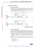
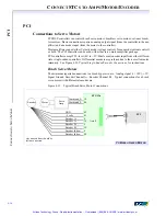
Most step drives require 3 wires for operation: step, direction and ground (or + 5V). The con-
troller provides a TTL-level step pulse(+) output and dir) output for each axis. In ad-
dition, the complements of the step and direction are also provided (
Step-
,
Dir-
).
Some drives allow differential inputs in which both
Step+
and
Step-
lines are connected for
higher noise immunity. If in doubt, fax the driver data sheets or driver pinouts to
Motion Engi-
neering
along with any questions.
Note that when only
Step+
or
Step-
is used, it may be necessary
to jumper unused terminals on
the step drive
. Before connecting
Step+
or
Step-
, consult your step drive’s manual.
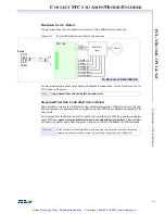
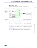
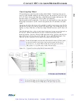
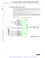
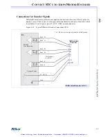
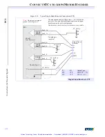
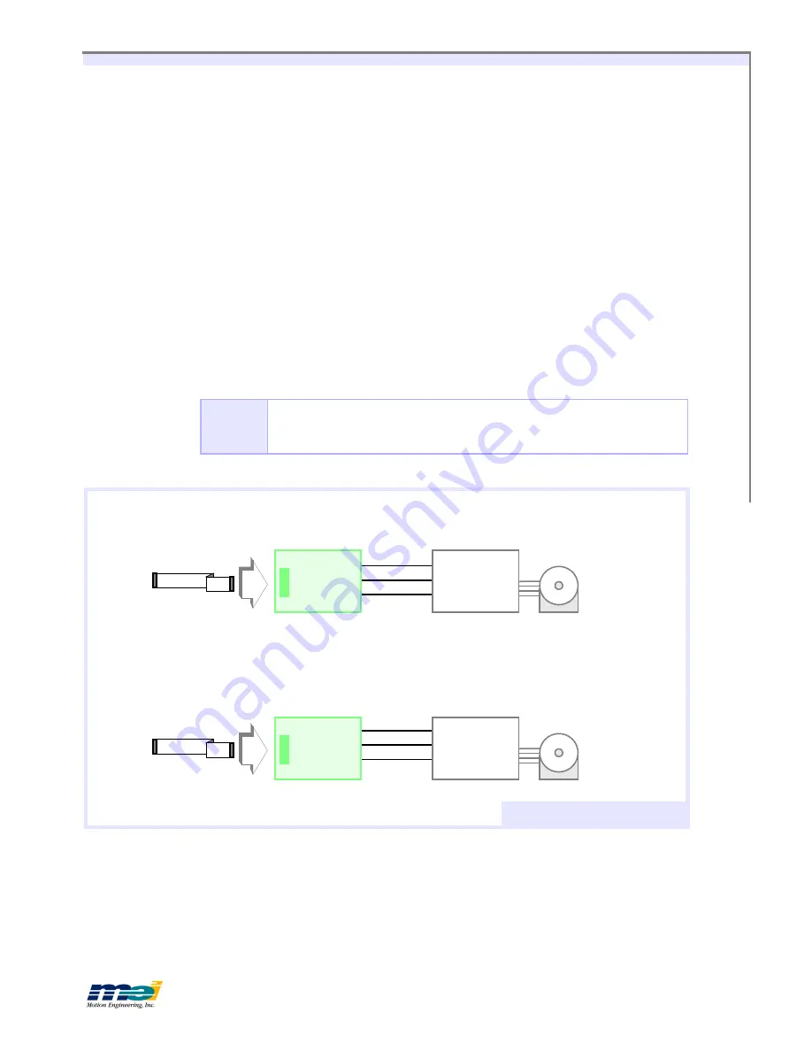
Figure 4-10
Typical Open-Loop Step Motor Connections
Note
If the controller is configured for
open loop step control
, make sure that the tuning
parameters conform to the parameters listed in
Open-Loop Stepper Systems
(on page
6-7 in Chapter 6).
M
OTOR
M
OTOR
STC-50
STC-50
23
21
17
17
23
19
Step -
Step +
GND
STEP
DIR
GND
STEP
DIR
S
TEP
D
RIVE
This connection is for step drives that trigger on
the
falling edge
.
This connection is for step drives that trigger on
the
rising edge
.
From
104
LC
From
104
LC
S
TEP
D
RIVE
TO
O
PEN
-
LOOP
S
TEP
M
OTORS
Artisan Technology Group - Quality Instrumentation ... Guaranteed | (888) 88-SOURCE | www.artisantg.com

