


C
ONNECT
STC
S
TO
A
MPS
/M
OTOR
/E
NCODER
4-14
L
C
,
1
0
4
C
o
n
n
ec
ti
o
n
s
to
S
te
p
M
o
to
rs
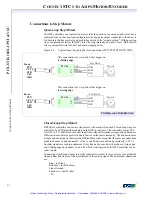
Closed-loop Step Motors
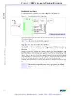
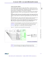
DSP Series controllers can control step motors with encoder feedback. Closed-loop steps are
controlled by a PID algorithm running on the DSP in real time. The controllers accept TTL-
level (0V to +5V, 40mA max) encoder input from either differential or single-ended encoders.
Differential encoders are preferred due to their excellent noise immunity. The connections for
a single-ended encoder are identical to a differential encoder except, nothing should be con-
nected to channel A- and channel B-. (The A- and B- lines are pulled up internally to 2.5V).
Encoder signals are read in quadrature. Every line on the encoder will produce a rising edge
and a falling edge on channels A+ and B+, which is interpreted by the DSP controller as 4 en-
coder counts.
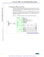
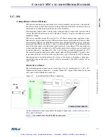
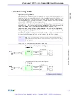
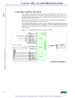
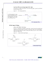
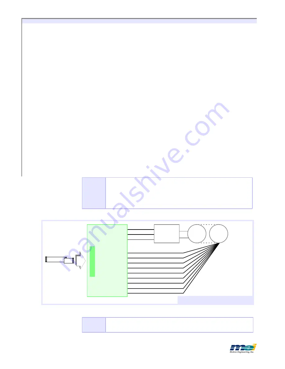
Connecting closed-loop step motors to the controller is similar to servo motors, except that the
step and direction lines are connected instead of the analog signal. The minimum connections
are:
Step+ (or Step-)
Di (or Direction-)
Signal Ground
Encoder A+ and B+ lines
+ 5V
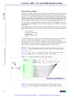
Note that when only
Step+
or
Step-
is used, it may be necessary
to jumper unused terminals on
the step drive
. Before connecting
Step+
or
Step-
, consult your step drive’s manual
In general, use
Step+
for drives with active high logic, and use
Step-
for drives with active low
logic. Both
Step+
and
Step-
lines can be connected to drives with differential inputs. If in
doubt, fax the drive pinouts to Motion Engineering along with any questions.
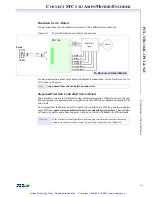
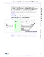
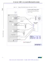
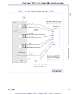
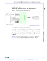
Figure 4-11
Typical Connections for Closed-Loop Step Motor
Warning!
For the best performance, ensure that the ratio is between the
encoder resolution
(counts per revolution) and the
step resolution
(steps per microsteps per revolution)
is 1:4.
Lower ratios (1:1, 1:2) will be difficult to tune and will have poor static stability.
Higher ratios (1:6, 1:8) will have poor constant velocity stability.
Note
For drives that trigger on the rising edge of the pulse input, use
Step+
.
For drives that trigger on the falling edge of the pulse input, use
Step-
.
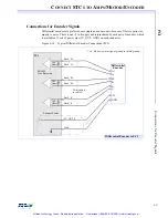
GND
+5 volts
-5 volts
Encoder A+
Encoder A-
Encoder B+
Encoder B-
Encoder Index+
Step +
GND
Step
Drive
Motor
Encoder
STC-50
Dir
17
23
19
1
18
4
2
10
6
8
12
Encoder Index-
14
T
O
C
LOSED
-
LOOP
S
TEP
M
OTOR
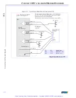
From
104
LC
Artisan Technology Group - Quality Instrumentation ... Guaranteed | (888) 88-SOURCE | www.artisantg.com


