C
ONNECT
STC
S
TO
D
ISCRETE
I/O
5-2
D
ed
ic
a
te
d
a
n
d
U
se
r
I/
O
N
o
te
s
O
p
to
-I
so
la
ti
o
n
Dedicated and User I/O Notes
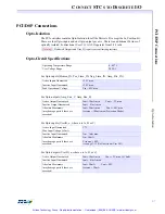
Opto-Isolation
(PCX, V6U, 104X, CPCI, STD only)
Dedicated and User I/O headers (connectors) conform to Opto-22/Grayhill/Gordos standard
pin arrangement, and may be connected directly. Some Opto-22 racks do not use the +5V logic
power on pin 49 of the I/O connector, and in those cases, +5V must be provided from an ex-
ternal source). Grayhill racks can be configured to take the +5V logic power from pin 49, so
that no external source is necessary.
When the DSP Series controllers are powered up, the User I/O signals and Dedicated outputs
come up
Low
. Most opto-isolation modules invert the I/O signals, which means that I/O signals
may come up
High
. The active level of the Dedicated I/O signals can be configured in Motion
Console; the boot configurations of the User I/O signals can be set using the function libraries.
Refer to the
DSP Series C Programming Reference.
Output Wiring
User I/O outputs are driven by an Intel 82C55
Programmable Peripheral Interface Controller
.
When power is supplied to the 82C55, these outputs have 3 possible output states:
•
High Impedance
(High Z) (1 micro amp leakage current)
•
High
( >3.0V at 2.5 milliamp source current)
•
Low
( < 0.4V at 2.5 milliamperes sink current)
If there is no power to the 82C55, the output state is held low by input protection diodes.
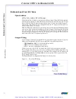
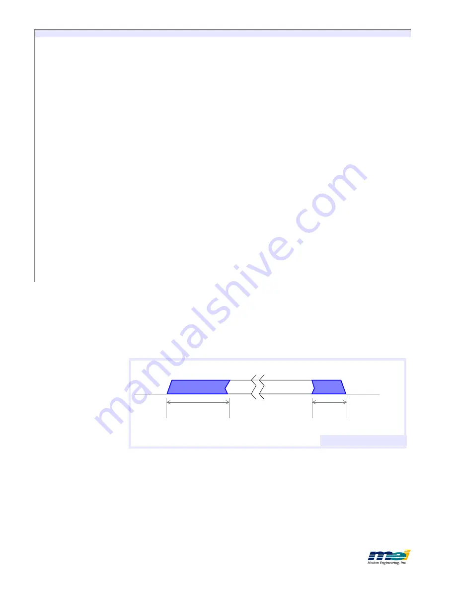
The next figure shows the
power-on
and
power-off
timing of the controller output states. Ap-
proximately 0.3 to 0.5 seconds after power is supplied to the computer, the User outputs will
go to the
Power-On
state. The
Power-On
state can be any one of the 3 output states of the
82C55 (High Z, High or Low).
The
Power-On
state is configured at the factory to be the
Low
state.
Figure 5-1
Power On/Off Timing
.3-.5 sec
<.1 sec
Power-On
Power-Off
Low
High Z
User-Defined
High Z
Low
Power On/Off Timing
Artisan Technology Group - Quality Instrumentation ... Guaranteed | (888) 88-SOURCE | www.artisantg.com

