


C
ONNECT
STC
S
TO
D
ISCRETE
I/O
5-6
H
o
m
e
a
n
d
L
im
it
S
w
it
ch
W
ir
in
g
W
ir
in
g
E
xa
m
p
le
s
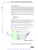
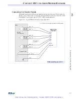
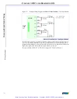
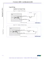
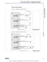
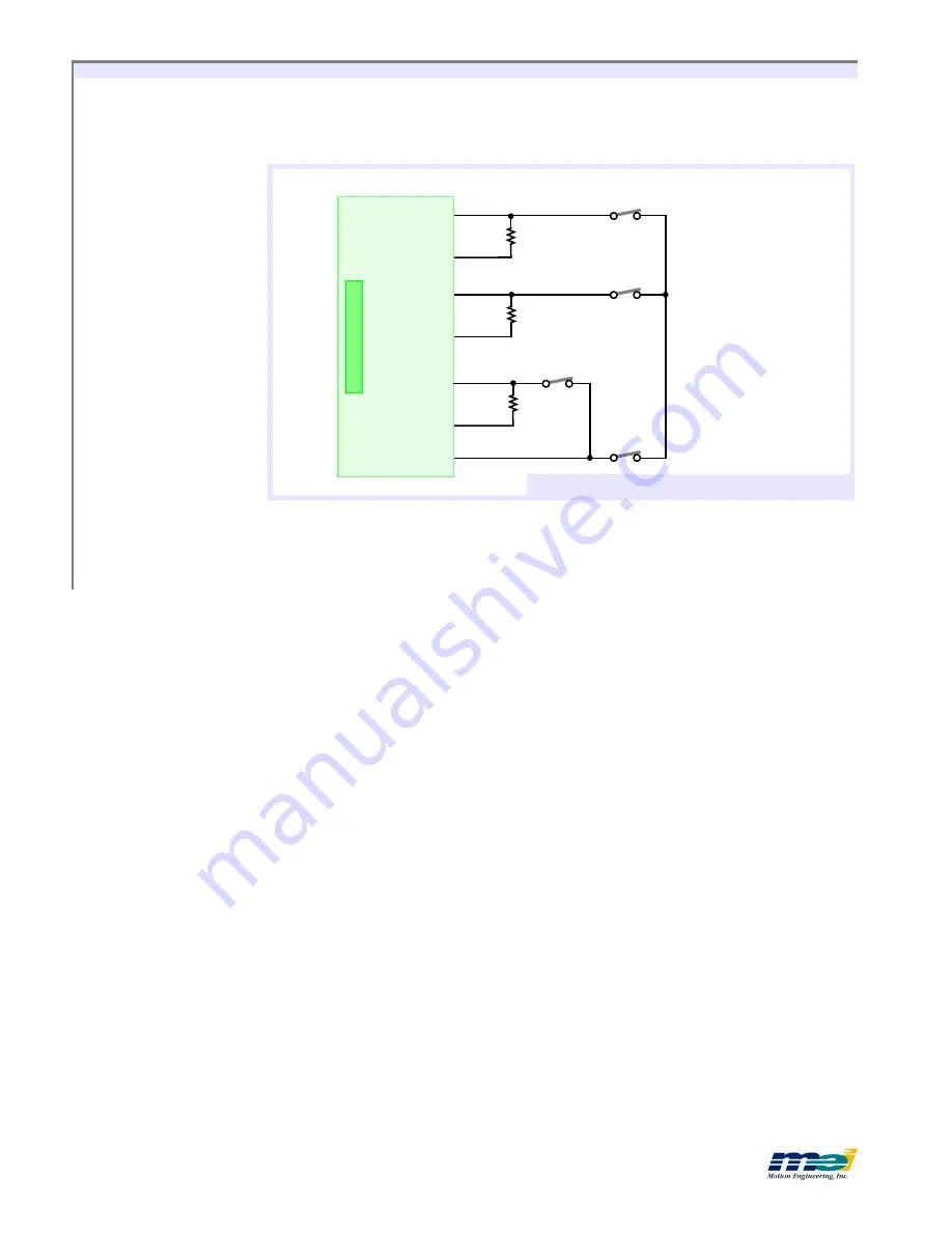
Figure 5-7
Example Wiring Diagram for
104 & LC Limit Switches
- Non Opto-Isolated
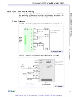
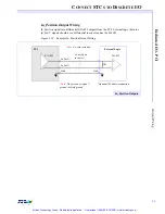
Fail-safe limit operation is provided for both the optically isolated and non-isolated limit cir-
cuits. If a wire breaks in the limit circuit, the associated limit is activated and the motion is
stopped until the problem is corrected. Since the controller can be configured for either active
high or low inputs, other limit and home sensor circuits can be used.
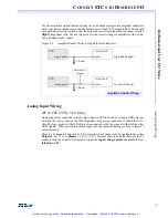
For opto-isolation with the LC or 104, refer to
Appendix F, OptoCon Reference.
POS
GND
NEG
GND
HOME
POS Limit
NEG Limit
E-Stop
220 Ohm
220 Ohm
220 Ohm
Home
STC-50
From
104
LC
27
49
29
49
31
1
49
+5 V
*Note:
Limit Switches
are Normally Closed
104 & LC Limit Switch - Non Opto-Isolated
GND
Artisan Technology Group - Quality Instrumentation ... Guaranteed | (888) 88-SOURCE | www.artisantg.com


