A-1
A
PPENDIX
A
M
ORE
A
BOUT
W
IRING
Wiring Servo Motors
DSP Series controllers can control brush servo motors, brushless servo motors, or linear brush/
brushless motors. Basic connections require an analog output signal (from the controller to the
amplifier) and an encoder input (from the motor to the controller).
Velocity/Torque Mode
Most amplifiers support either Velocity mode (voltage control), Torque mode (current control)
or both. The DSP controller can be used with either servo motor/amplifier package. Generally,
velocity mode is more stable than torque mode.
When the amplifier is in Velocity mode, the velocity of the motor is proportional to the analog
input voltage (-10V to +10V). When the amplifier is in Torque mode the current applied to the
motor is proportional to the analog input voltage (-10V to +10V).
Encoder Input
DSP Series controllers accept TTL-level (0V to +5V, 40mA max) encoder input from either dif-
ferential or single-ended encoders. Differential encoders are preferred due to their excellent
noise immunity. When used with differential encoders, the differential line receiver on the con-
Wiring Servo Motors
Velocity/Torque Mode
A-1
Encoder Input
A-1
Brush/Brushless Servo Motors
A-2
Step-and-Direction Controlled Servo Motors
A-2
Wiring Step Motors
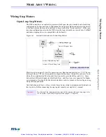
Open-Loop Step Motors
A-3
Direction Pulse Synchronization
A-4
Closed-Loop Step Motors
A-4
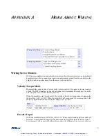
Mode
Velocity
velocity
of motor
is proportional to
analog input voltage
Torque
current
applied to motor
(-10V to +10V)
Artisan Technology Group - Quality Instrumentation ... Guaranteed | (888) 88-SOURCE | www.artisantg.com

