M
ORE
A
BOUT
W
IRING
A-3
W
ir
in
g
S
te
p
M
o
to
rs
O
p
en
-L
o
o
p
S
te
p
M
o
to
rs
Wiring Step Motors
Open-Loop Step Motors
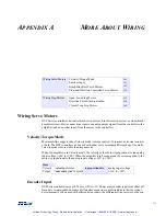
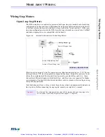
The DSP controllers can control step motors in both open-loop (no encoder) and closed-loop
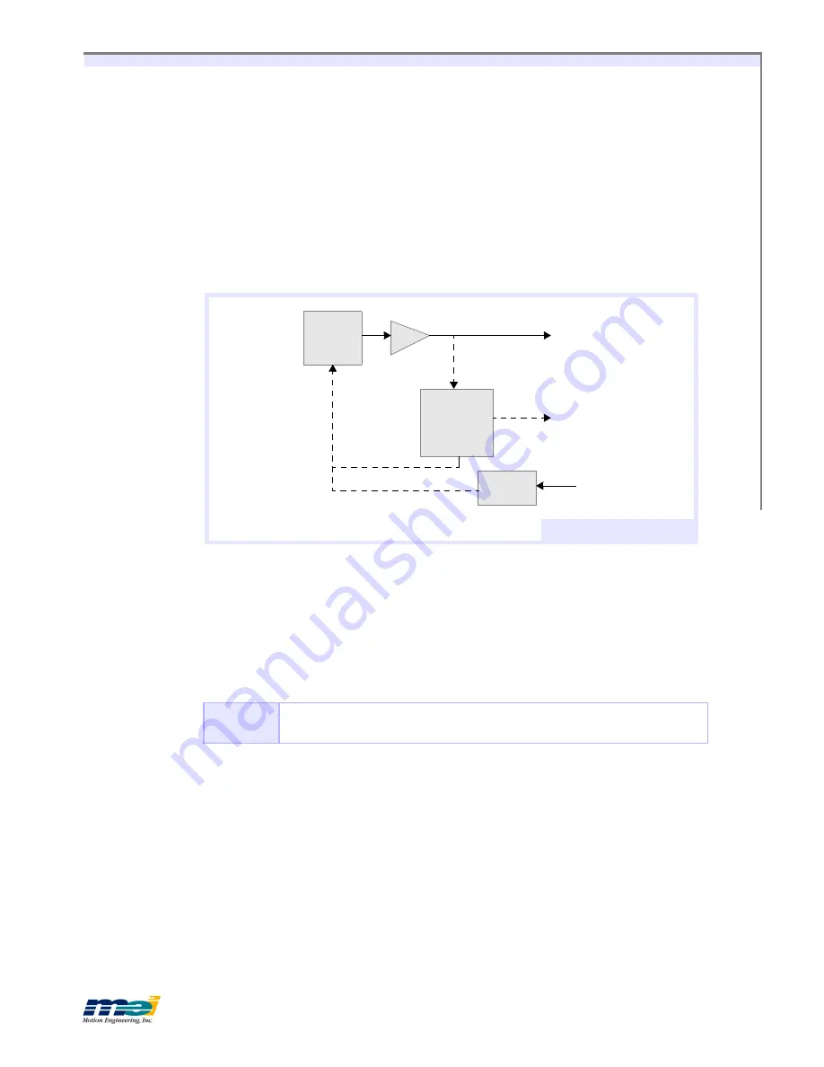
configurations. In the open-loop configuration the step pulse output (connected to the driver)
is fed back into the line receivers and used to keep track of the “actual position.” With open-
loop step configuration selected, the DSP closes the loop internally on a pair of axes. Full/half
and micro stepping drives are compatible with the boards.
Figure A-1
Internal Architecture to Control Step Motors
Most step drives require 3 wires for operation: step, direction and ground (or + 5V). The con-
troller provides a TTL-level step pulse(+) output and dir) output for each axis. In ad-
dition, the complements of the step and direction are also provided (
Step-
and
Dir-
). Some
drives allow differential inputs in which both
Step+
and
Step-
lines are connected for higher
noise immunity. If in doubt, fax the driver data sheets or driver pinouts to
Motion Engineering
along with any questions.
Note that when only
Step+
or
Step-
is used, it may be necessary to jumper unused terminals on
the step drive. Before connecting the step inputs, consult your step drive’s manual.
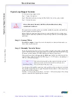
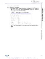
Important!
For a listing of the tuning parameters required for motion with open-loop steps, refer
to
Test System: Open-Loop Stepper Systems
(page 6-7, Chapter 6)
PID
Filter
Voltage
to
Frequency
Converter
Analog Output
Active if Stepper Axis
Step
Output
Encoder
Inputs
Active if Open-Loop Axis
Active if Closed-Loop Axis
I
NTERNAL
A
RCHITECTURE
D/A
Artisan Technology Group - Quality Instrumentation ... Guaranteed | (888) 88-SOURCE | www.artisantg.com

