background image

19

18

The system must be installed on a firm, load-bearing and dry wall. 

The distance to the collectors must be chosen to prevent overheating 

of the station. Risks due to adjacent structural components, 

electrical cables, gas, water or heating pipes must be 

avoided. Ensure free access to the station, safety fittings and 

connection pipes and cables.

1.

Choose installation site

2.

Mark drillholes on the wall by means

of installation and fixing bracket (A).

3.

Make drillholes and knock in anchors/Rawl plugs

4.

Screw on station with insulation subsection

5.

Pipeline binding without tension manufacture

Before assembling the modules of the single-line solar station,

 remove the insulation and lift the module from the retainer clip. 

The lower mounting hole (behind the flow meter) is accessible 

after removing the module. Once the insulation has been installed, 

put the module back into the retainer clip. 

Check if it is attached firmly.

Top shut-off fittings
The top shut-off fittings are equipped with integrated, 
manually openable backflow preventer.
The direction of flow is indicated by a stylised arrow shape on the spindle.
(Chapter 3, see. fig. 1)

Upper shut-off fittings

The upper shut-off fittings are fitted with integrated, 

manually adjustable backflow preventers. 

The flow direction or position is visible through the bevelled 

side (see fig. ). 

If the flow direction is not observed, 

the back flow preventer can act against the intended flow direction 

and thus block the flow.

Operating state with active backflow preventers (see. fig.): 

- Ball valve: Solar return (cold, solar pump line) upwards (Position 1)

- Ball valve (two-line): Solar flow (hot) downwards

3.1 


Wall-mounted installation

3.2 Shut-off fittings

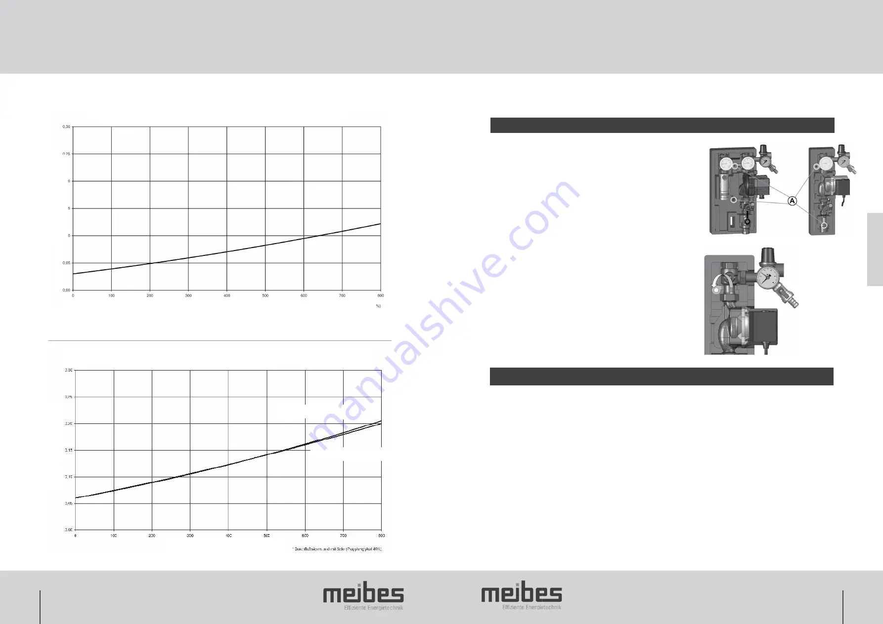
Pressure loss (bar)

Volumetric flow l/h 

Volumetric flow - pressure loss diagram Two-branch solar station Type S

Volumetric flow - pressure loss diagram Single branch solar station Type S

Volumetric flow l/h 

Pressure loss (bar)

GB

with permanent permanent catcher

without permanent permanent catcher

2. Technical Data

3. Installation

Summary of Contents for Solar station S

Page 1: ...l information for installation and operation GB Station solaire S Documentation technique pour le montage et la mise en service FR Technische Information f r Montage und Betrieb Effiziente Energietech...

Page 2: ...g nderung und Pr fung elektrischer Ger te VDE 0185 Allgemeines f r das Errichten von Blitzschutzanlagen VDE 0190 Hauptpotentialausgleich von elektrischen Anlagen VDE 0855 Installation von Antennenanla...

Page 3: ...geben Das ausf hrende bzw zugelassene Gewerke z B Installateur hat dem Kunden die Wirkungsweise und Bedienung des Ger tes verst ndlich zu erkl ren 1 2 Bestimmungsgem e Verwendung 1 3 Erstinbetriebnahm...

Page 4: ...unbeabsichtigtes Schlie en gesichert sein Die Bet tigung ist nur von geschulten Fachpersonal vorzunehmen F r den Betrieb der Anlage m ssen die Kugelh hne komplett ge ffnet sein Kapitel 3 erste Abb Obe...

Page 5: ...anuell ge ffnet werden vgl Abs 3 2 Dieses ist vor allem beim Entleeren der Anlage zu beachten und anzuwenden Die Markierung der Flie richtung Pfeilrichtung befindet sich auf der Spindel des Kugelhahne...

Page 6: ...C sein damit besteht erh hte Verbr hungsgefahr Der Entl fter sitzt am h chsten Punkt der Anlage Nach dem sorgf ltigen und fachgerechten Entl ften ist der Anlagen druck jeweils wieder auf den Betriebsd...

Page 7: ...hes hinter grundbeleuchtetes schwarz wei Display Bedienung ber Dreh Dr cksteller und ESC Taste 3 Eing nge f r PT 1000 F hler Analog bzw PWM Ausgang f r Hocheffizienzpumpe Drehzahlregelung ein vorkonfi...

Page 8: ...tial conductors VDE 0185 General information for the installation of lightning protection systems VDE 0190 Main equipotential bonding of electrical systems Additional guidelines and notes VDI 6002 Par...

Page 9: ...d 1 2 Intended use 1 3 Initial commissioning 1 4 Working on the system 1 5 Liability The solar station S is supplied pre assembled as a 1 or 2 branch type with or without high efficiency pump Optional...

Page 10: ...is attached firmly Top shut off fittings The top shut off fittings are equipped with integrated manually openable backflow preventer The direction of flow is indicated by a stylised arrow shape on th...

Page 11: ...x 45 see Fig 9 from the end of position Bear this in mind and use it especially when draining the system Cracking pressure ever approx 300 mm water column 0 Ball valve open non return valve in operati...

Page 12: ...ed be sure the pipeline system is completely drained The heat transfer fluid should be collected in a suitable container and disposed of according to the manufacturer s instructions in an environmenta...

Page 13: ...th Grundfos UPM3 Hybrid 15 70 PWM With Wilo Yonos Para ST 15 7 PWM with permanent air vent Without pump With Grundfos UPM3 Hybrid 15 70 PWM With Wilo Yonos Para ST 15 7 PWM 45705 24 EA 45705 94 45705...

Page 14: ...e en service de mat riaux lectriques mise la terre conducteurs de protection con ducteurs d quipotentialit VDE 0185 g n ralit s concernant la mise en service d installations de protection contre la fo...

Page 15: ...aux prescriptions 1 3 Initial commissioning 1 4 Travaux sur l installation 1 5 Responsabilit La station solaire est livr e en unit pr fabriqu e avec 1 ou 2 lignes avec ou sans pompe haut rendement R...

Page 16: ...ixation V rifiez la fixation Vannes d arr t sup rieures Les vannes d arr t sup rieures sont quip es de freins Clapet anti retour int gr s et r gler manuellement Le sens d coulement est marqu par une f...

Page 17: ...liquer surtout lors de la vidange de l installation Cracking pressure ever approx 300 mm water column Pression d ouverture env 2x 200 mm colonne d eau 0 Robinet ouvert clapet anti retour en fonctionne...

Page 18: ...V rifier l tanch it des branchements composants et raccordements En cas de fuites vider l installation effectuer les r parations et recommencer l essai de pression 4 4 Vidange Lors de la vidange de l...

Page 19: ...de remplissage et de vidange possibilit de raccordement un vase d expansion au c t aspiration de la pompe d bitm tre affichage double du m lange de propyl ne glycol 40 et de l eau Comme ci dessus mai...

Page 20: ...39 38...

Page 21: ......

Reviews: