MeiG
Product
Manual
of
SLM750
Module
SLM750
Module
Hardware
Design
Page 34, total 84 pages
Figure 4 Power requirements for burst transmission
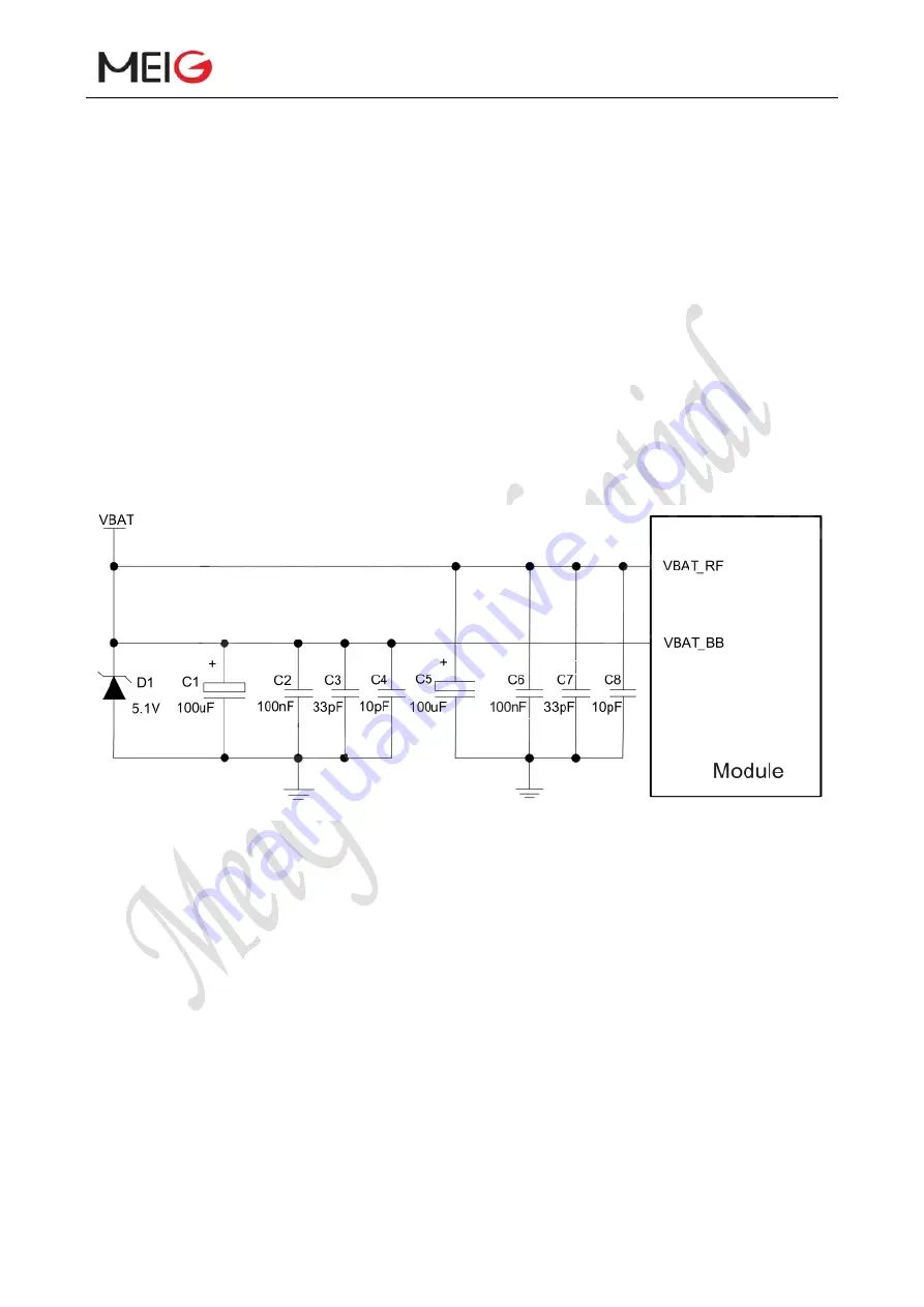
In order to reduce voltage drop, a low ESR 100uF filter capacitor is needed. The multilayer
ceramic capacitor (MLCC) has the best ESR, suggestion to add three ceramic capacitors (100nF,
33pF, 10pF) to VBAT_BB and VBAT_RF pins, and the capacitors should be placed close to the
VBAT pin. When external power supply makes connection to module, VBAT_BB and VBAT_RF
need to apply star line. VBAT_BB line width should not be less than 1 mm, and VBATRF line
width should not be less than 2 mm. In principle, the longer the VBAT line, the wider the line width.
In addition, in order to ensure the stability of the power supply, it is recommended to add a
Zener diode at the front end of the power supply with a power of 5.1V and a work and power of
0.5W or higher. The reference circuit is as follows:
Figure 5 Star structure of power supply
3.6.3 Reference design for power supply
The power design for the module is very important as the performance of the module largely
depends on the power supply. The power supply is capable of providing sufficient current up to 2A
at least. If the voltage drop between the input and output is not too high, it is recommended that you
use a LDO to supply power for the module. If there is a big voltage difference between the input
and the output, DCDC is preferred to be used as a power supply.
The following figure shows a reference design for +5V input power supply. The designed
output for the power supply is +3.3V (typical value 3.8V) and the maximum load current is 3A.


