MeiG
Product
Manual
of
SLM750
Module
SLM750
Module
Hardware
Design
Page 52, total 84 pages
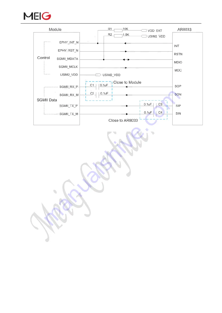
Figure 23 Reference Circuit of SGMII Interface with PHY AR8033 Application
In order to enhance the reliability and availability in your application, please follow the criteria
below in the Ethernet PHY circuit design:
Keep SGMII data and control signals away from RF and VBAT trace.
Keep the maximum trace length less than 25.4cm and keep skew on the differential pairs less
than 0.7mm.
The differential impedance of SGMII data trace is 100 ohm±10%.
SGMII RX/TX line spacing is at least 3 times width, SGMII signal distance from other signal
lines is to maintain at least 3 times line width.
SGMII RX modules already have 0.1uf capacitors and do not need to be added externally
3.17 Wireless Connectivity Interfaces
SLM750 supports a low-power SDIO 3.0 interface for WLAN and a PCM interface for BT.
The following table shows the pin definition of wireless connectivity interfaces.
Table 20: Pin Definition of Wireless Connectivity Interfaces


