background image

13

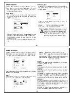
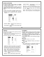
SPEED : Adjusts the pull-in speed of ATW.
DELAY CNT : Sets the time-based hysteresis of

ATW.

ATW FRAME : Sets the pull-in frame magnification.
ENVIROMENT : Sets the pull-in frame of ATW.

(indoor or outdoor)

PUSH :

Adjusts the white balance regardless of the subject
condition.(Pull-in mode)

USER1 :

Manually adjusted white balance by User mode1.

USER2 :

Manually adjusted white balance by User mode2.

ANTI CR :

Minimizes the color changes(color rolling) over long
periods caused by very small differences between
the flicker frequency of non-inverter fluorescent lights
and the drive frequency of the image sensor devices.

MANUAL :

Function allows the white balance to be adjusted
manually following the black body radiation curve.
The R gain is adjusted automatically in tandem with
the up/down setting of the B gain.

PUSH LOCK :

Function for locking the WB gain after PUSH(pull-in)
control and shutting down the pull-in control.

WHITE BALANCE

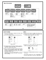
1) Press the Set button to display the Setup menu.
2) Position the cursor at LENS and press the left

or right button to select the white balance mode.

Seven white balance control modes can be selected
according to conditions.

ATW :

Automatically tracks the changes in the color temp
-perature, and adjusts the white balance.

SETUP MENU

LENS

AUTO

SHUTTER/AGC

AUTO

WHITE BAL

ATW

BACKLIGHT

OFF

PICT ADJUST
ATR

OFF

MOTION DET

OFF

NEXT
EXIT

SAVE ALL

ATW

SPEED

239

DELAY CNT

016

ATW FRAME

x2.00

ENVIROMENT INDOOR

RETURN

12

SHUTTER/AGC

1) Press the Set Button to display the Setup menu.
2) Position the cursor at SHUTTER/AGC and press

the left or right button to select the Auto mode
or Manual mode setting.

AUTO Mode

When using the

Auto I

ris lens, the brightness of

the picture image will be controled by setting the
Brightness level.

In SHUT+AUTO IRIS mode, shutter speed is

auto

-

matically varied acccording to the incident light.

The brightness indicates DC level of DC lens in High
Luminance mode.
In Low Luminance mode, brightness indicates AGC
level.

Note :

Outdoor illumination levels may exceed

150,000 lux, which is outside the range
that can be controlled by the electronic
shutter. For proper operation of elect
-ronic shutter, If illumination levels ex-
ceed 10,000 lux, use a auto-iris lens.

!

AUTO SETUP

HIGH LUMINANCE

MODE

SHUT+AUTO IRIS

BRIGHTNESS

024

LOW LUMINANCE

MODE

AGC

BRIGHTNESS x0.50

RETURN

MANUAL Mode

When using the

Manual I

ris lens, the brightness of

the picture image will be controled by setting the
shutter level.

In Manual mode, Shutter and AGC level will be
changed as follows.

Shutter

: 1/60 to 1/100,000sec (8 stage)

AGC level : 6dB to 44.8dB (8 stage)

MANUAL SETUP

MODE

SHUT+AGC

SHUTTER

1/60

AGC

x6.00

RETURN

Summary of Contents for SI-C600N

Page 1: ...tenance servicing instruc tions in the literature accompanying the appliance WARNING TO PREVENT THE RISK OF FIRE OR ELECTRIC SHOCK HAZARD DO NOT EXPOSE THIS CAMERA TO RAIN OR MOISTURE Due to design modification data given in this instruction book are subject to possible change without prior notice Information for USA This device complies with Part 15 of the FCC Rules Changes or modifications not a...

Page 2: ...cabinet and the back or bottom are provided for ventilation and to insure reliable operation of the product and to protect it from overheating and these openings must not be blocked or covered The openings should never be blocked by plac ing the product on a bed sofa rug or other similar surface This product should not be placed in a built in installation such as a book case unless proper ventilat...

Page 3: ...dirt with a dry soft cloth If it is extremely dirty use furniture cleaning tissue Do not use alcohols petroleum distillates liquid cleaners or sprays Daily check Make daily check for proper operation for surveil ance use In order to maintain normal operation the output of camera should be checked by user everyday for a clear and focused picture 5 FEATURES High sensitivity 1 2 412 000 pixels CCD wi...

Page 4: ...ting base Mounting base for installing the camera 7 Power indicator Lights up when the camera is powered Video output connector BNC connector that outputs a composite video signal Setup buttons When use setting up and adjusting the camera with reference to the on screen menu See page 9 S VIDEO connector Output connector for separat ed Y C video signal Connect to the S VIDEO input connector of vide...

Page 5: ...ccommodate usage conditions When connected to a monitor convenient on screen menus facilitate checking and changing the settings and adjustments A brief help lines is often presented on the screen below the list of commands The complete set of current parameters is saved and will be loaded each time turn on the camera until the next time change the setup The setting menus are illustrated on the ne...

Page 6: ... to select the Lens mode 3 Position the cursor at AUTO and press the Set button to setting for Auto Iris Lens 4 Press the Left Right Up Down button to setting the Lens After setting position the cursor at RETURN and press the Set button to return to Setup Menu SETUP MENU LENS AUTO SHUTTER AGC AUTO WHITE BAL ATW BACKLIGHT OFF PICT ADJUST ATR OFF MOTION DET OFF NEXT EXIT SAVE ALL AUTO IRIS TYPE DC M...

Page 7: ...adjusts the white balance SETUP MENU LENS AUTO SHUTTER AGC AUTO WHITE BAL ATW BACKLIGHT OFF PICT ADJUST ATR OFF MOTION DET OFF NEXT EXIT SAVE ALL ATW SPEED 239 DELAY CNT 016 ATW FRAME x2 00 ENVIROMENT INDOOR RETURN 12 SHUTTER AGC 1 Press the Set Button to display the Setup menu 2 Position the cursor at SHUTTER AGC and press the left or right button to select the Auto mode or Manual mode setting AU...

Page 8: ...2 Position the cursor at PICT ADJUST and press the Set button to adjust the video output signal MIRROR Sets the horizontal flip for the display output BRIGHTNESS Sets the brightness of video output signal CONTRAST Sets the contrast of video output signal SHARPNESS Sets the sharpness of video output signal HUE Sets the HUE color of video output signal GAIN Sets the chroma gain of video output signa...

Page 9: ...he screen 1 Position the cursor at Privacy and press the left right button to set Privacy ON 2 Press the Set button to enter the Privacy setup AREA SEL Selects the mask frame to be adjusted TOP Sets the top side of the mask frame BOTTOM Sets the bottom side of the mask frame LEFT Sets the left side of the mask frame RIGHT Sets the right side of the mask frame COLOR Sets the color of the mask frame...

Page 10: ...ng Night operations BW BURST ON IR OPTIMIZER ON MODE AUTO LEVEL 015 RETURN 19 NOISE REDUCTION Noise reduction is a function that reduces the image noise in order to improve the image quality of the camera In particular it reduces the noise whichis generated under low brightness shooting conditions and other high gain states 1 Position the cursor at NR and press the Set button to setting the noise ...

Page 11: ...The OSD menu displays support 7 languages English Japanese German French Russian Spanish and Portuguese Position the cursor at LANGUAGE and press the left right button to select a language The menus can be changed in real time in the selected language MENU CONFIGURATION CONFIDENTIAL OFF JOUR NUIT AUTO REDUCT BRUIT ID CAMERA OFF SYNC INT LANGUAGE FRANCAIS REINIT CAMERA BACK QUITTER SAVE ALL 21 CAME...

Page 12: ...ctor When installing a video iris lens lens switch should be set to VIDEO position When installing a galvanometric iris lens lens switch should be set to DC position ADJUSTING AUTO IRIS LENSES Make this adjustment after connecting the camera to a power source and a monitor 1 Set AGC mode to off 2 When using a Video type lens Adjust the level control on the lens to pro duce minimum smear and optimu...

Page 13: ...r use out doors or in very bright conditions When using a lens with an ND filter attached Shooting may not be possible with the mini mum required illumination specified 24 WITH A ZOOM LENS 1 Fully open the aperture and set the lens to the maximum tele photo position Then turn the focus ring to focus In the case of an auto iris lens only shoot a comparatively dark object so that aperture is fully o...

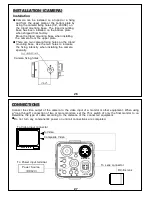
Page 14: ...unting base Use the two holes to increase the fixing intensity when installing the camera specially Camera fixing holes 27 CONNECTIONS Connect the video output of the camera to the video input of a monitor or other equipment When using a loop through connection of two or more monitors set the 75Ω switch of only the final monitor to on Determine the type of cable according to the distance of the co...

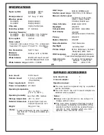
Page 15: ...00N NTSC SI C600P PAL Pickup element 1 2 Sony IT CCD Effective pixels SI C600N 768 H X494 V SI C600P 752 H X582 V Chip size 7 4 H X5 95 V mm Scanning system 2 1 interlace Scanning frequency SI C600N Hor 15 734kHz Ver 59 94Hz SI C600P Hor 15 625kHz Ver 50Hz Sync system Internal Video output Composite video signal 1Vp p 75Ω unbalanced Separated Y C signal Y 1Vp p 75Ω C 0 286Vp p 75Ω Hor Resolution 5...

Page 16: ...30 MEMO ...
Reviews: