Page 10
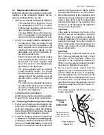
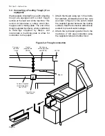
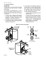
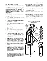
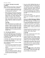
Figure 3-12: Drain connection
Machine
drain
Rubber boot
(supplied)
Clamp
(supplied)
2” OD drain line
(supplied by others)
S
ECTION
3 - I
NSTALLATION
3.9 Drain Connection
IMPORTANT
In some cases, local codes dictate that drain
connections be made only by a certified
professional.
The machine is equipped with a 1-15/16”
(50mm) OD vertical, gravity-fed drain. The
machine requires a 4” floor drain. See Figures
3-3 and 3-6.
1. In some cases, a grease trap (supplied
by others) must be fitted into the waste
water line. If a trap is required for your
installation, check that it is present.
2. If possible, the machine drain can simply
be positioned directly above a floor drain,
as shown in Figure 3-12.
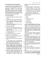
3. If a floor drain is not directly beneath the
machine drain, or if local codes require a
trap, a drain line can be attached using
the supplied rubber boot and clamp. A
2” OD drain pipe is recommended.
Choose a piping material that:
•
Complies with any applicable local and
national codes.
•
Is rated for use with water temp-
eratures up to the machine’s warmest
water connection (140°F is recom-
mended for the dewatering press
rinsing system - see
Section 3.8,
Water Supply Connections
)
•
Is rated for 3-12 pH.
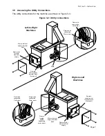
Route to floor drain
(4” drain recommended)
Drain
Left-to-Right
Machines
Right-to-Left
Machines
Drain
handle
Drain is
located
behind
dewatering
press motor
Drain
handle


