


6 Connectors and LEDs in the rear slot cover
6.2 SUB-D Pin Assignments of Multiref Port
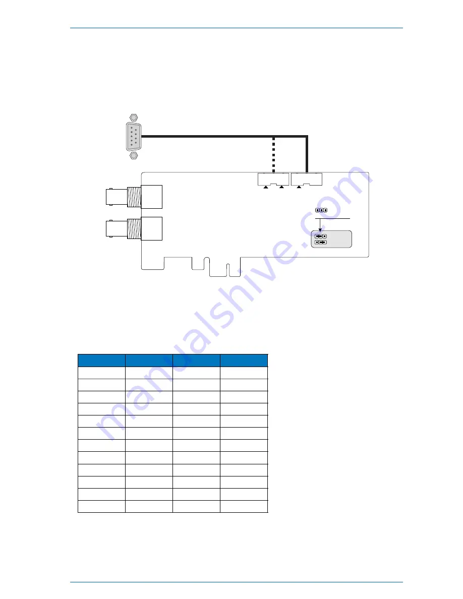
Connection of ribbon cable
To lead the „Multiref“ signals through the SUB-D connector, the ribbon cable must be plugged to the appro-
priate boxed header:
5
9
1
6
SUB-D
connection:
Multiref Port
SUB-D
connection:
Standard Port
Time Code (TC) Jumper
TC active high
TC active low
SUB-D pin assignment
The following list shows the pin assignmenmt of the SUB-D connecter with ribbon cable in the „Multiref“
position. Some signals are only connected to the SUB-D if the specified DIP-switch is „ON“.
Multiref Port
DIP 3 must be OFF
DIP 9 must be OFF
DIP 10 must be OFF
DIP 5 must be OFF
D-SUB-PIN
Signal
Signal Level
DIP-Switch
1
VCC out
+5V
1
2
RxD1 in
RS232
-
3
TxD1 out
RS232
-
4
PPO_1 (PPM)
TTL
5
4
10MHz out
TTL
10
5
GND
-
-
6
CAP0 in
TTL
2
7
PPS in
TTL
7
8
PPO_0 (PPS)
TTL
4
9
CLK in
TTL
6
7
CAP1 in
TTL
3
9
PPO_2 DCF out
TTL
9
DIP 7 must be OFF
DIP 6 must be OFF
GPS180PEX
Date: 28th March 2018
13


