11 Technical Appendix
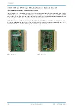
11.8.20.1 BPE - Backplane Port Expander
Please Note:
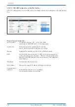
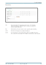
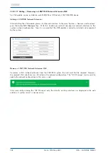
In principle, it should be noted that the signals that are provided via a BPE at the various connectors are
always generated by the upstream clock and spread via the backplane of the system. In opposite to the CPE,
the signals are not generated by the module and therefore the outputs can only be set via the receiver.
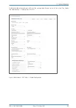
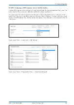
The selection and settings of the signals such as frequency, time code or programmable pulse outputs can
be done via the web interface menu "Clock" or "Clock Switch Card "(for redundant systems).
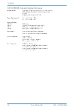
Output Signals:
fixed TTL signals:
10 MHz, PPS, IRIG DCLS, IRIG AM, 2.048 MHz,
PPOs (selectable via receiver)
Output Level:
5 V
pp
without load
2.8 - 3.0 V
pp
into 50
Ω
Power Requirements:
5 V +-5%, 150 mA / BNC
5 V +-5%, 150 mA / FO
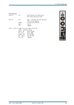
Status Indicators
LED St:
BPE status
LED In:
Status of the backplane’s output signals
LED A:
BPE status - output signals (1 + 2)
LED B:
BPE status - output signals (3 + 4)
Note:
When pulse trains >= 1.6 s are configured,
the LED assigned to the output remains "red"
as these pulse trains are not monitored
(e.g. PPM, PPH ...).
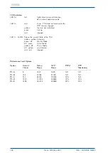
Initialisation:
LED St: blue until USB is configured
LED In - LED B: off until USB is configured
USB is configured:
LED St: blue
LED In - LED B:
0,5 sec. red -> 0,5 sec. yellow ->
0,5 sec. green -> 0,5 sec. off
Normal Operation:
LED St. + LED In: green
LED A: green, if the desired signal is present
on output 1 and output 2
LED B: green, if the desired signal is present
on output 3 and output 4
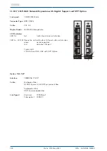
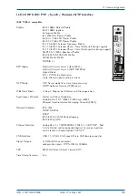
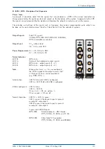
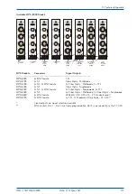
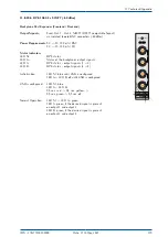
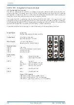
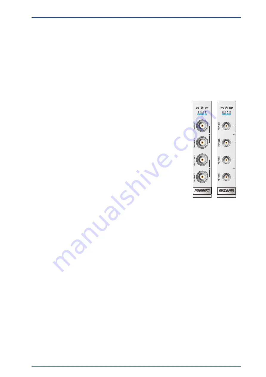
Figure right: BPE Outputs
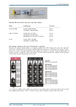
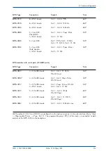
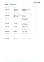
BPE-2000
Standard outputs - BNC female:
PPS, 10 MHz, TC DCLS and TC AM
BPE 5000
Fiber Optic ST-Connectors
PPS, 10 MHz, TC DCLS und 2048kHz
IMS - LANTIME M4000
Date: 27th May 2021
111

