11 Technical Appendix
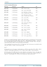
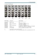
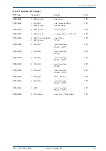
BPE Type
Connectors
Signals
Size
BPE-2110
8 x BNC female
Out 1 - Out 8: PPS
8HP
BPE-2120
8 x BNC female
Out 1 - Out 8: 10 MHz
8HP
BPE-2180
8 x BNC female
Out 1 - Out 8: 2048 kHz
8HP
BPE-2500
4 x 2pin DFK
Out 1 - Out 4: Progr. Pulse
4HP
PhotoMOS
1 x BNC female
Out 5 - TC AM
BPE-2600
4 x 2pin DFK
Out 1: PPS, Out 2: 10 MHz
4HP
Out 3: TC DCLS, Out 4: TC AM
BPE-2700
4 x 2pin DFK
Out 1 - Out 4: Progr. Pulses
4HP
Opto Coupler
1 x BNC female
Out 5 - TC AM
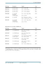
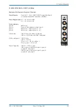
BPE modules with serial ports (D-SUB9 jacks)
BPE Type
Connectors
Signals
Size
BPE-3014
2 x D-SUB9 female
Out 1, Out 2: TC DCLS
4HP
RS-422 Level
BPE-3050
4
2 x D-SUB9 female
Out 1, Out 2: Progr. Pulse
4HP
RS-422 Level
BPE-3412
1 x D-SUB9 female
Out 1: Progr. Pulses, RS-422
4HP
2 x BNC female
Out 2, Out 3: TC AM
BPE-3422
4 x D-SUB9 female
Out 1 - Out 4: 1MHz
8HP
RS-422 Pegel
BPE-3424
4 x D-SUB9 female
Out 1 - Out 4: TC DCLS
8HP
RS-422 Pegel
BPE-3082
4 x D-SUB9 female
Out 1 - Out 4: 2048 kHz sine
8HP
(4)
The outputs COM A and COM B are configured via the upstream receiver in the web interface (Menu "Clock
→
Programable Pulses
→
Prog. Out 1"). The programable pulses PP_0 of the clock are connected to both
outputs of the BPE-3050 via the backplane.
IMS - LANTIME M4000
Date: 27th May 2021
113

