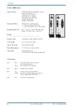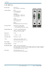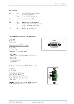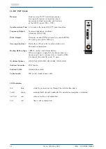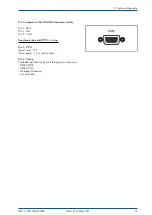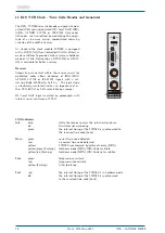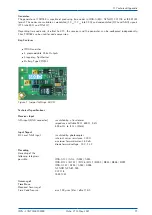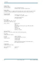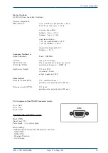
11.8.11.1 RSC180 - DIP Switch
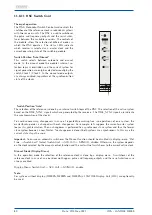
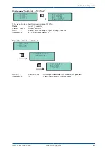
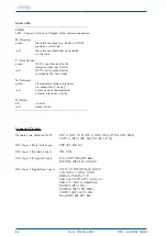
Various modes of the board can be additionally configured by an on-board DIP-Switch.
Configuration of a DIP-Switch
SW
NAME
Description
————————————————————————————————————————
1
DIS_ENA
enable / disable activation of signals if both clocks are async
2
DIS_MAN
enable / disable a manual override by front panel switches
3
DIS_REM
enable / disable the remote control
4
FUNCTION
RSC board functionality: either in an IMS system or LAN interface is activated
5
Reserve
6
Reserve
7
Reserve
8
DIS_MST
enables / disables the priority master clk selection
9
Clk1_Clk2
selects between the priority master clk 1 or clk 2
10
EN_CLK
activates the clock with a sync event after reset (only if DIP 1 is ON).
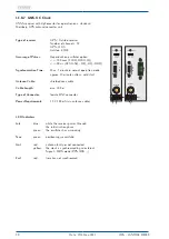
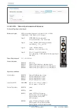
Figure: DIP-Switch of RSC180
Description of DIP_SW positions:
Switch No. 1. Positions:
(0)
OFF:
In the case that both clock are async, all output signals are disabled.
(1)
ON:
Even if both clocks are async, outputs are activated from one of the clocks.
Switch No. 2. Positions:
(0)
OFF:
Front panel switch functions activated.
(1)
ON:
Front panel switch functions disabled.
Switch No. 3. Positions:
(0)
OFF:
Remote control activated.
(1)
ON:
Remote control disabled.
Switch No. 4. Positions:
(0)
OFF:
The RSC board is used in an IMS system.
(1)
ON:
LAN Interface is activated.
Switch No. 5-7 Reserves.
Switch No. 8. Positions:
(0)
OFF:
The Priority master mode is disabled.
(1)
ON:
Priority master mode is enabled.
82
Date: 27th May 2021
IMS - LANTIME M4000

