background image

12 Attachment: Technical Information

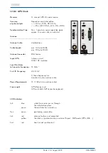
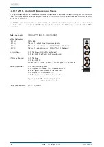
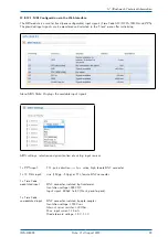
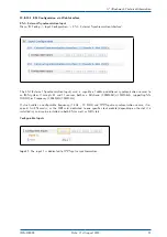
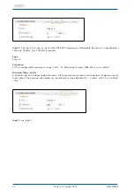
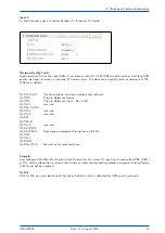
Holdover Mode

Automatic switching
to crystal time base

accuracy approximately 1E-8
if decoder has been synchronous for more than 1h

Backup Battery

If the power supply fails, an onboard realtime clock keeps time and date information important system
parameters are stored in the RAM of the system lifetime of the Lithium battery at least 10 years

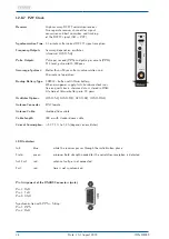
Generator Outputs

Modulated output:

unbalanced sine carrier, 1 kHz
3 V

PP

(MARK), 1 V

PP

(SPACE) into 50

unmodulated outputs(DCLS):
TTL into 50

, RS-422

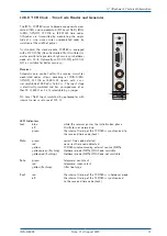
Pulse Outputs

Four programmable outputs, TTL level
Default settings: active only ’if sync’

PPO_0 - PPO_3:

Idle (not active)
Timer
Single Shot
Pulse Per Second, Per Minute, Per Hour (PPS, PPM, PPH)
DCF77 Marks
Time Sync
DCLS Time Code
Synthesizer Frequency

Accuracy of Pulses

Better than

±

1

µ

sec after synchronization and 20 minutes of operation

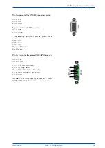
Serial Port

Configurable RS-232 interface

Baudrates:

300 Bd...115200 Bd

Framing:

7E2, 8N1, 8N2, 8E1, 7N2, 7E1, 801

Mode of operation:

string per second
string per minute
string on request

Time telegram:

Meinberg Standard, Uni Erlangen, SAT, Meinberg Capture,
ION, Computime, SPA, RACAL

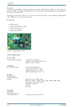
Capture Inputs

Triggered by falling TTL slope

Pulse repetition time:

1.5 msec min.

Resolution:

800 nsec

IMS-M4000

Date: 21st August 2019

39

Summary of Contents for IMS-M4000

Page 1: ...MANUAL IMS M4000 Modular Sync System and NTP Server 21st August 2019 Meinberg Funkuhren GmbH Co KG ...

Page 2: ......

Page 3: ...Front view Frontansicht IMS M4000 ...

Page 4: ...rface 15 9 The Menues in Detail 16 9 1 Root Menu 16 10 The graphical user interfaces 18 11 The WEB Interface 19 12 Attachment Technical Information 20 12 1 Technical Specifications LANTIME M4000 Housing 20 12 2 IMS M4000 Chassis 22 12 3 Retrofitting the Active Cooling Module ACM 23 12 4 Available Modules and Connectors 24 12 5 TERMINAL Console 25 12 6 USB Connector 25 12 7 Replacement or Installat...

Page 5: ... 64 12 8 17 IMS PIO PPS oder 10MHz I O Module 66 12 8 18 CPE and BPE Output Modules Frontend Backend Eurocard 68 12 8 19 LIU Line Interface Unit 85 12 8 20 LNO 10MHz Sinus Output Module 93 12 8 21 REL1000 Error Relay Module 95 12 8 22 FDM Frequency Deviation Monitoring 97 12 8 23 SCG U Studio Clock Generator 99 12 8 24 SCG B Studio Clock Generator Balanced 101 12 8 25 VSG Video Sync Generator 103 ...

Page 6: ...unkuhren GmbH Co KG Lange Wand 9 31812 Bad Pyrmont Germany Phone 49 0 52 81 93 09 0 Fax 49 0 52 81 93 09 230 Internet https www meinbergglobal com Mail info meinberg de Date 2019 08 16 Version 1 11 IMS M4000 Date 21st August 2019 1 ...

Page 7: ...e in a maximum ambient temperature of 40 C The building in equipment may not be opened Protection against fire must be assured in the end application The ventilation opening may not be covered For AC Supply 100 240 V AC The building in equipment is a class 1 equipment and must be connected to an earthed outlet TN Power System For safe operation the building in equipment must be protected by max 16...

Page 8: ...struction of high voltage devices 2 2 Supply Voltage WARNING This device is powered by a dangerous voltage Nonobservance of the safety instructions of this manual may lead to serious damage to persons and property and to danger to life Installtion commissioning maintenance and operation of this device are to be carried out by qualified personnel only The general safety instructions and standards e...

Page 9: ... Hints Antenna WARNING DANGER TO LIFE BY ELECTRICAL SHOCK Make sure to comply with the occupational health and safety standards when installing the antenna Never work without a proper fall protection device Do not carry out any installation or maintenance work on the antenna system or cabling when there is a potential risk of lightning Surge Voltage Protector Due to extremely high currents associa...

Page 10: ...acturer must be used for replacement The waste battery has to be disposed as proposed by the manufacturer of the battery 2 6 Grounding connection M4000 To ensure a safe operation and to fulfil the require ments in accordance with IEC 60950 1 the system must be correctly connected to an equipotential grounding bus On the upper left side of the chassis a ground ing connector is provided The mounting...

Page 11: ...P address netmask and default gateway To get an overview of the current configuration press F2 from main menu Press F2 again to enter SETUP configuration page Please ask your administrator for propper TCP IP configuration Interfaces Global Cfg Services Use Up and Down to select Port lan0 0 1 of 1 172 100 000 001 OK Then press 3 times the OK button to change to IPV4 ETH0 configuration page to enter...

Page 12: ... be configured from the front panel of LANTIME The network address or the equivalent name of LANTIME has to be shown to all NTP clients in the TCP IP network As well as NTP the Linux system also supports a number of further network protocols HTTP S FTP SSH and Telnet Because of this remote configuration or status requests can come from any WEB browser This access via the network can be deactivated...

Page 13: ... cable between antenna and receiver depends on the attenuation factor of the coaxial cable Up to four GNSS receivers can be run with one antenna downconverter unit by using an optional antenna splitter The total length of an antenna line from antenna to receiver must not be longer than the max length shown in the table below The position of the splitter in the antenna line does not matter The opti...

Page 14: ... sheet of the used cable 5 2 Antenna Short Circuit systems with front display only In case of an antenna line short circuit the following message appears in the display ANTENNA SHORT CIRCUIT DISCONNECT POWER If this message appears the clock has to be disconnected from the mains and the defect eliminated After that the clock can be powered up again The supply voltage for the antenna converter unit...

Page 15: ...acket Normally you connect the antenna converter directly with the antenna cable to the system GPS Antenna free view to the sky Cable Slot N Norm female N Norm male N Norm male N Norm female N Norm female N Norm male Meinberg GPS N Norm male female or BNC male female as short as possible Ground lead to PE rail Protective Earth Cable ca 1 5 mm Ø fastened at the surge protector 10 Date 21st August 2...

Page 16: ... of band rejection and lower elevation pattern performance than traditional patch antennas Their unique radome shape sheds water and ice while eliminating problems associated with bird perching This antenna is made of materials that fully comply with provisions stipulated by EU directives RoHS 2002 95 EC The antenna provides integrated lightning protection capability The antenna also features ESD ...

Page 17: ...ion Danger to life due to fall Pay attention to effective working safety when installing antennas Never work without an effective anti fall equipment WARNING Working on the antenna system during thunderstorms Danger to life due to electrical shock Do not carry out any work on the antenna system or the antenna cable if there is a risk of a lightning strike Do not carry out any work on the antenna s...

Page 18: ... antenna is less suitable for stationary installations Figure Installation drawing RV 76G antenna WARNING Antenna mounting without effective anti fall protection Danger to life due to fall Pay attention to effective working safety when installing antennas Never work without an effective anti fall equipment WARNING Working on the antenna system during thunderstorms Danger to life due to electrical ...

Page 19: ...nce clocks usually the hardware clock of the single board computer and the integrated receiver clock The message NTP sync to local is displayed until synchronization is complete For the synchronization of the NTPD with the time reference it is necessary that the receiver is synchronous with the incoming time signal In this case the following message is monitored on the display NORMAL OPERATION NTP...

Page 20: ...set to 38400Baud 8N1 VT100 emulation Once the IPv4 address net mask and IPv4 GATEWAY have been set up or the network interface has been automatically configured with DHCP Autoconf further configuration changes can be done via a network connection To set up a TELNET connection the following commands are entered replace 198 168 10 10 with the IP of your LANTIME telnet 198 168 10 10 LANTIME IP addres...

Page 21: ...UTC time zone will be monitored in the bottom line If the IGNORE LOCK option is enabled an will be shown behind the time The multicolor LEDs will reflect the current state of the device Ref Time green the reference clock e g integrated GPS produce valid time red the reference clock produce no valid time e g not synchronized Time Service green NTP has been synchronized to reference clock red NTP is...

Page 22: ...be displayed when pressing the UP and DOWN arrow buttons sync to GPS NTP Offs 3us Fri 15 01 2013 UTC 12 00 00 Ref Time Time Service Network System Setup MRS Info GPS Setup GPS Set Outputs External NTP Local Strat Restart NTP PTP IEEE1588 Time Zone Restart Factory Reset Ref Time Time Service Network System Ref Time Time Service Network System Ref Time Time Service Network System Services Interfaces...

Page 23: ...rts a broad range of browsers we recommend Mozilla Firefox The WEB Interface The web interface can be used by more than one user in parallel but the two or more running sessions may influence each other We explicitly do not recommend the parallel usage of the configuration interfaces Connect to the web interface by entering the following address into the address field of your web browser http 198 ...

Page 24: ...ification of this certificate is possible during the first session see chapter The Web Interface Security HTTPS Certificate After entering the right password the main menu page shows up This page contains an overview of the most important configuration and status parameters for the system System information and Status messages Information about LANTIME model and software Network information first ...

Page 25: ... M4000 Housing Housing 19inch 4U metal chassis Optimized for ETSI rackmount 300mm 21 inch or 19 inch standard rack Protection Rating IP20 Physical Dimensions 483 mm wide x 177 mm high x 274 mm deep Ambient Temperature 0 50 C Humidity 85 max 20 Date 21st August 2019 IMS M4000 ...

Page 26: ...ossible then the system must be equipped with an active cooling module ACM See chapter Retrofit the System with an Active Cooling Module ACM The left Figure shows the expected air flow during device in operation without ACM active cooling mod ule and with space between devices for ventilation 1U at the bottom and the top In the right figure the air flow during device in operation with ACM and no s...

Page 27: ...Winkelsatz für die ETSI Rackmontage geliefert wer den Beim Einbau ist hier daruf zu achten dass die Haltewinkel an allen gekennzeichneten Punkten mit den im Lieferumfang enthaltenen Schrauben befestigt werden Die Abbildung unten zeigt die physikalischen Abmessungen des M4000 Gehäuses 22 Date 21st August 2019 IMS M4000 ...

Page 28: ...function keys are located you will find an empty slide in bay on the right and on the left side To pull out the empty slide in bays carefully introduce a tool e g small screwdriver into the indicated slots and press out the module from its anchoring The new Active Cooling Modules are already equipped with a front plate Simply slide in the ACM mod ule into the guide rail and push until it locks int...

Page 29: ...n DFK male 20 72 VDC 5pin MSTB clamp Network LNE GbE RJ45 10 100 1000 MBit shielded data line TSU GbE HPS100 RJ45 10 100 1000 MBit shielded data line SFP 10 100 1000 MBit shielded data line Signal Outputs CPE configurable BNC DFK 2 PPOs serial TS TC FO shielded data line DSUB9 ST BPE fixed BNC ST PPS 10MHz TC 2 048kHz shielded data line LIU RJ45 jack E1 T1 balanced 120 Ohm Clock shielded data line...

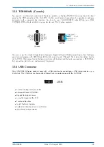
Page 30: ...re your terminal program with 38400 Baud 8 Databits no parity and 1 Stopbit The terminal emulation have to set to VT100 After connecting to the timeserver there will be displayed the login message press RETURN for first connection default user root password timeserver 12 6 USB Connector Most LANTIME M Series products come with a USB interface for connectiong a USB storage device e g a USB stick Th...

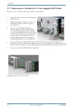
Page 31: ...tor block of the housing You need a certain amount of force to release the module from this link Once the connection to the connector block of the system s backplane is loosened the module can be easily pulled out 3 When installing the new IMS module please ensure that the board is correctly inserted into the two guide rails of the system housing Non observance can cause damage to the module and t...

Page 32: ...e in operational mode The following applies to the individual IMS slots I O ESI and MRI Slots hot swappable CLK1 CLK2 hot swappable but a rescan of the reference clocks Rescan Refclocks must be executed in the web interface menu System after the exchange or installation of a clock module CPU The central management unit is not hot swappable i e the system must be disconnected from mains before repl...

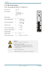
Page 33: ...r Pmax 50 W Maximum thermal energy Etherm 180 00 kJ h 170 61 BTU h N L AD10 PWR U 100 240V N U 265V max 90 I 1 0 A N f 50 60Hz N U 100 200V N U 250V max 90 I 0 6 A N 1 5 WARNING This equipment is operated at a hazardous voltage Danger to life due to electrical shock Only qualified personnel electricians may connect the device Never work with open terminals and plugs while the power is on All conne...

Page 34: ... Maximum thermal energy Etherm 180 00 kJ h 170 61 BTU h DC20 PWR U V N 24 48 U V max 20 60 I 2 1 A N 2 4 12 8 3 Power Supply 10 36 V DC Connector 5pin DFK Pin Assignment 1 not connected 2 VIN 3 PE Protective Earth 4 VIN 5 not connected Input Parameter Nominal voltage range UN 24 V Maximum voltage range Umax 10 36 V Nominal current IN 2 5 A Output Parameter Maximum power Pmax 50 W Maximum thermal e...

Page 35: ...V DC insulated Local Oscillator to Converter Frequency 10 MHz 1 First IF Frequency 35 4 MHz 1 1 these frequencys are transfered via the antenna cable Power Requirements 15 V 100 mA via antenna cable Figure right GPS Receiver and GPS with XHE SPI Connector optional LED Indicators Init blue while the receiver passes through the initialization phase green the oscillator has warmed up Nav green positi...

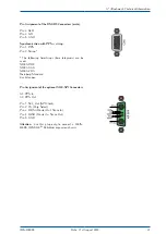
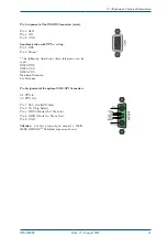
Page 36: ...me telegrams can be used NMEA RMC NMEA GGA NMEA ZDA Meinberg Standard Uni Erlangen Pin Assignment of the optional XHE SPI Connectors A1 PPS In A2 PPS Out Pin 1 SCL_Out SPI Clock Pin 2 CS Chip Select Pin 3 MOSI Master Out Slave In Pin 4 MISO Master In Slave Out Pin 5 GND Attention Use this plug only to connect a MEIN BERG IMS XHERb Rubidium expansion chassis IMS M4000 Date 21st August 2019 31 ...

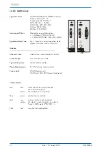
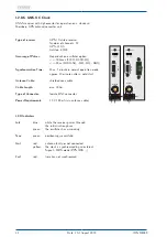
Page 37: ... Antenna Antenna Cable shielded coax cable Belden H155 PE Cable Length max 70m low loss cable Type of Connector female SMA connector Power Requirements 5 V 100 mA via antenna cable Figure right GNSS Receiver and GNSS with XHE SPI Connector optional LED Indicators Init blue while the receiver passes through the initialization phase green the oscillator has warmed up Nav green positioning successful...

Page 38: ...me telegrams can be used NMEA RMC NMEA GGA NMEA ZDA Meinberg Standard Uni Erlangen Pin Assignment of the optional XHE SPI Connectors A1 PPS In A2 PPS Out Pin 1 SCL_Out SPI Clock Pin 2 CS Chip Select Pin 3 MOSI Master Out Slave In Pin 4 MISO Master In Slave Out Pin 5 GND Attention Use this plug only to connect a MEIN BERG IMS XHERb Rubidium expansion chassis IMS M4000 Date 21st August 2019 33 ...

Page 39: ...tart Antenna Cable shielded coax cable Cable Length max 300m Type of Connector female BNC connector Power Requirements 15 V 100 mA via antenna cable LED Indicators Init blue while the receiver passes through the initialization phase green the oscillator has warmed up Nav green positioning successfully Ant red antenna faulty or not connected yellow the clock is synchronized by an external Signal MR...

Page 40: ...me telegrams can be used NMEA RMC NMEA GGA NMEA ZDA Meinberg Standard Uni Erlangen Pin Assignment of the optional XHE SPI Connectors A1 PPS In A2 PPS Out Pin 1 SCL_Out SPI Clock Pin 2 CS Chip Select Pin 3 MOSI Master Out Slave In Pin 4 MISO Master In Slave Out Pin 5 GND Attention Use this plug only to connect a MEIN BERG IMS XHERb Rubidium expansion chassis IMS M4000 Date 21st August 2019 35 ...

Page 41: ...ware clock runs free on quartz basis almanac data is stored in RAM Life time of lithium battery min 10 years Oscillator Options OCXO SQ OCXO MQ OCXO HQ OCXO DHQ Antenna Connector BNC female Antenna Cable shielded Coax cable Cable Length 300 m with standard coax cable Current Consumption 5 V 1 1 A to 1 4 A depends on oscillator LED Indicators Init blue while the receiver passes through the initiali...

Page 42: ...r amplitude of 600 mVpp to 8 Vpp The input stage is electrically insulated and has an impedance of ei ther 50 Ω 600 Ω or 5 kΩ selectable by a jumper DC Level Shift Input insulated by optocoupler with internal series resistance of 220 Ω LED Indicators Init blue while the receiver passes the initialization phase off Oscillator not warmed up green the internal timing of the TCR180 is synchronized to ...

Page 43: ...r Battery Type CR2032 Figure 1 Jumper Settings 600 Ω Technical Specifications Receiver Input AM input BNC connector insulated by a transformer impedance settable 50 Ω 600 Ω 5 kΩ 600 mVPP to 8 VPP Mark Input Signal DC Level Shift input insulated by photocoupler internal series resistance 220 Ω maximum forward current 60 mA diode forward voltage 1 0 V 1 3 V Decoding Decoding of the following telegra...

Page 44: ...lse Outputs Four programmable outputs TTL level Default settings active only if sync PPO_0 PPO_3 Idle not active Timer Single Shot Pulse Per Second Per Minute Per Hour PPS PPM PPH DCF77 Marks Time Sync DCLS Time Code Synthesizer Frequency Accuracy of Pulses Better than 1 µsec after synchronization and 20 minutes of operation Serial Port Configurable RS 232 interface Baudrates 300 Bd 115200 Bd Fram...

Page 45: ...hronous to pulse per second 10 kHz to 10 MHz deviation of frequency 0 0047 Hz Synthesizer Outputs TTL into 50 Ω sine wave 1 5 Vrms output impedance 200 Ω Pulse Outputs Pulse per second PPS TTL and RS 232 level positive pulse pulse duration 200 msec Pulse per minute PPM TTL level positive pulse pulse duration 200 msec Power Requirement power supplies provided via VG Connector 5 V 450 mA Dimension E...

Page 46: ...ed on the TIME_SYNC signals which are generated by the receivers The TIME_SYNC signals are indicate the synchronization of the clocks To avoid unnecessary changeovers in case of repeatedly occurring free run operations of one system the master backup order is changed with each changeover For example let s suppose the current master system looses its synchronization Then a changeover is performed t...

Page 47: ...OK This menu displays the status information of the RSC Mode manual automatic remote Clock 1 Clock 2 State of receivers PSU1 PSU2 State of power supplies MUX enabled disabled 1 2 enabled disabled disabling output signals during a free run 1 2 selected reference clock Menu Switch Unit RSC Cntl REMOTE enable disable Switching between automatic and remote operation OUTPUTS enabled disabled Disabling ...

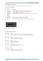
Page 48: ...ority master clk 1 or clk 2 10 EN_CLK activates the clock with a sync event after reset only if DIP 1 is ON Figure DIP Switch of RSC180 Description of DIP_SW positions Switch No 1 Positions 0 OFF In the case that both clock are async all output signals are disabled 1 ON Even if both clocks are async outputs are activated from one of the clocks Switch No 2 Positions 0 OFF Front panel switch functio...

Page 49: ...e Priority master is clock 1 1 ON The Priority master is clock 2 IF Switch No 1 is ON Switch No 10 Positions 0 OFF Even async one clock is always enabled 1 ON A clock is enabled after the first sync event since a reset 44 Date 21st August 2019 IMS M4000 ...

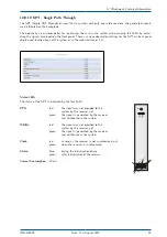
Page 50: ...m or in the web interface or CLI Status LEDs The status of the SPT is indicated by the four LEDs PPS red the signal was not provided to the system by the receiver yet green the signal is generated by the receiver and distributed in the system 10MHz red the signal was not provided to the system by the receiver yet green the signal is generated by the receiver and distributed in the system Clock red...

Page 51: ...nsumption Typ application 6 9 W 5V Technical Specifications IMS CPU C15G2 LTOS V7 only Processor Intel R AtomTM Processor E Series 2 Cores 1 33GHz TDP 3W Main Memory onboard 2MB Cache Memory 1MB 2nd Level Cache Flash Disk 4 GB Network Connectors 1 x 10 100 1000 Base T with RJ45 Jack 1 x 1000Base T with SFP Jack Power Consumption Typ application 6 9 W 5V Interfaces IMS LAN CPU Serial Interface RJ45...

Page 52: ...p red at least one of the monitored network interfaces is faulty A Alarm off no error red general error Supported Protocols Network Time Protocol NTP NTP v2 RFC 1119 NTP v3 RFC 1305 NTP v4 RFC 5905 SNTP v3 RFC 1769 SNTP v4 RFC 4330 OSI Layer 2 Data Link Layer PRP IEC 62439 3 OSI Layer 3 Network Layer IPv4 IPv6 OSI Layer 4 Transport Layer TCP UDP TIME RFC 868 DAYTIME RFC 867 SYSLOG OSI Layer 7 Appl...

Page 53: ...TC DCLS Status Indicators LED St MRI status LED In Status of the backplane s reference signals LED A Status of the input signals TC AM DCLS at the board LED B Status of the input signals 10MHz PPS at the board Initialisation LED St blue until USB is configured LED In LED B off until USB is configured USB is configured LED St blue LED In LED B 0 5 sec red 0 5 sec yellow 0 5 sec green 0 5 sec off No...

Page 54: ...ection and prioritization of existing input sources 1 x PPS input TTL pulse duration 5µs active high female BNC connector 1 x 10 MHz input sine 1 5Vpp 5Vpp or TTL female BNC connector 1 x Time Code modulated input BNC connector isolated by transformer Insulation voltage 3000 VDC Input signal 600mV to 8 V Mark peak to peak 1 x Time Code unmodulated input BNC connector isolated by opto coupler Insul...

Page 55: ...ED St blue until configuration is done LED In off until configuration is done LED A off until configuration is done LED B off until configuration is done expiration LEDs ALL LEDs 0 5 sec red 0 5 sec yellow 0 5 sec green 0 5 sec off Normal Operation LED St green LED In green LED A green if PPS and 10MHz flashing green if only 10 MHz flashing yellow if only PPS off if no signal LED B green if Clock ...

Page 56: ...t accepts E1 and T1 sources both as a Bitstream 2 048MBit s 1 544Mbit s supporting SS M BOC or Frequency 2 048MHz 1 544MHz It also handles a configurable frequency 1 kHz 10 MHz and 1PPS pulse synchronization source if re quired An ESI card is as the MRI card dedicated to one specific clock module depending on the slot it is installed in and can be installed in both ESI as well as MRI slots Configu...

Page 57: ...nfigurable frequency in range 1 kHz 10 MHz of input signal 2048 kHz is set as default Maximum Slip n Cycles A discontinuity of an integer number of cycles in the measured carrier phase resulting from a temporary loss of input signal The maximum slip number can be selected in range between 0 5 3 cycles with 1 5 as a default value Input 3 see Input 2 52 Date 21st August 2019 IMS M4000 ...

Page 58: ... QL PRC Primary Reference Clock Rec G 811 QL INV3 reserved QL SSU A TNC QL INV5 reserved QL INV5 reserved QL ST2 QL SSU B QL INV9 reserved QL EEC2 ST3 QL EEC1 SEC Synchronous Equipment Timing Source SETS QL SMC QL ST3E QL PROV QL DNU DUS Do not use for synchronization Example User configured QL SSU B as Minimum Quality Level for his system E1 input signal coming from PRC G 811 or TNC will be allow...

Page 59: ...5 Cable CAT 5 0 Duplex Modes Half Full Autonegotiaton LED Indicators LED St Init lights blue during initialisation LED In LED B Shows the state of the four LAN ports after initialisation green normal operation red defective LAN port Figure right LNE GbE and LNE GbE with SFP Option LNE SFP 54 Date 21st August 2019 IMS M4000 ...

Page 60: ...k Speed Electrical 1000 Base T Fiber optical 1000 FX Recommended and tested Transceivers from other Vendors Mode Vendor Type Distance MULTI MODE AVAGO AFBR 5710PZ 550 m FINISAR FTLF8524P3BNL 500 m SINGLE MODE AVAGO AFCT 5710PZ 10 km FINISAR FTLF1318P3BTL 10 km SMARTOPTICS SO SFP L120D C63 80 km RJ 45 AVAGO ABCU 5740RZ 100 m FINISAR FCLF8521P2BTL 100 m IMS M4000 Date 21st August 2019 55 ...

Page 61: ... take an example where three LNE modules are inserted in a device Then the logical order of network interfaces assigned in a webinterface follows the MAC address order of LNE modules disregarding the I O slot order by which the modules are inserted In a factory assembling LNE modules are sorted in an ascending order starting from left to right see the corresponding figure above LAN 0 is therefore ...

Page 62: ...be used in 1000 MBIT HALF FULL duplex mode Indicate Link LED indication for the selected physical interface only if a front display with function keys is available Bonding to optimize the reliability and the use of a of higher bandwith IPv6 Mode This mode must be activated here MAC Address Displays the unique MAC address of the physical interface Assigned Virtual Interfaces In the Ethernet Interfa...

Page 63: ...network configurations Misc With the tab Misc the virtual interface can be assigned to a physical interface VLAN With VLAN this function can be enabled and configured Cluster The cluster function can be activated with this submenu and additional Parameters such as multicast or unicast mode TCP IP address and subnet mask can be set up here 58 Date 21st August 2019 IMS M4000 ...

Page 64: ...thernet HWaddr ec 46 70 00 8b 8c eth1 Link encap Ethernet HWaddr ec 46 70 00 8b 8d eth2 Link encap Ethernet HWaddr ec 46 70 00 8b 8e eth3 Link encap Ethernet HWaddr ec 46 70 00 8b 8f We are now sure that the LNE module is installed properly But as you can see in the lower figure the module is not implemented into the LTOS yet The figure shows the PHYSICAL NETWORK INTERFACES chapter of the NETWORK ...

Page 65: ... see the PHYSICAL INTERFACES will still show the LNE interfaces even if they already have been removed Now log in to the LANTIME Command Line Interface using SSH Telnet or a serial connection Once you are logged in exexute the following command nicmgr autoremove saveconfig network This will delete the interface out of the LANTIME configuration files After that the webinterface should display the o...

Page 66: ...ode E2E P2P Delay Mechanism Up to 128 messages second per client NTP Mode NTP Server mode 8 ns time stamp accuracy 1588 Clock Mode 1 Step 2 Step for both Master and Slave operation Synchronous Ethernet Master and Slave Capability Compliant to ITU T G 8261 G 8262 and G 8264 Ethernet Synchronization Messaging Channel ESMC Network Protocols IPv4 IPv6 DHCP DHCPv6 DSCP IEEE 802 1q VLAN filtering taggin...

Page 67: ... Shows the current State of the TSU yellow yellow Listening green off Master Mode off green Slave Mode yellow off Passiv Mode off yellow uncalibrated red red stopped Client Licenses License Unicast Delay NTP PTPv1 PTP Clients Req s Req s Monitoring PL A 8 1024 1600 NO NO PL B 256 32768 51200 NO NO PL C 512 65536 102400 YES NO PL D 1024 131072 204800 YES YES PL E 2048 262144 409600 YES YES 62 Date ...

Page 68: ...on A detailed configuration guide you will find in the corresponding firmware manual of the system See chapter The Web Interface Configuration PTP V2 Figure Webinterface PTP Menu Global Configuration IMS M4000 Date 21st August 2019 63 ...

Page 69: ...er client NTP Mode NTP Server mode 10 ns time stamp accuracy 1588 Clock Mode 1 Step 2 Step for both Master and Slave operation Synchronous Ethernet Master and Slave Capability Compliant to ITU T G 8261 G 8262 and G 8264 Ethernet Synchronization Messaging Channel ESMC Network Protocols IPv4 IPv6 DHCP DHCPv6 DSCP IEEE 802 1q VLAN filtering tagging Ethernet Interface Combo Port 1 x 100 1000BASE T RJ4...

Page 70: ... In red Error TSU does not work correctly PTP services stopped yellow No link but initialized green link up red stopped LED A LED B Shows the current State of the TSU yellow yellow Listening green off Master Mode off green Slave Mode yellow off Passiv Mode off yellow uncalibrated red red stopped IMS M4000 Date 21st August 2019 65 ...

Page 71: ...utput signals LED P display for preset PPS LED C display for preset 10MHz Initialisation LED St blue until USB is configured LED In LED B off until USB is configured USB is configured LED St blue LED In 0 5 sec red 0 5 sec yellow 0 5 sec green 0 5 sec off Normal Operation LED St LED In green LED P green if card is preset to PPS LED C green if card is preset to 10MHz 180 PIO I O 1 I O 2 I O 3 I O 4...

Page 72: ... 10MHz the card must be removed and the jumper position adjusted Via the web interface each port can be set separately to Input or Output If a port is set to Output the system PPS or the 10 MHz reference frequency is output signal at this port If a port is set to Input the incoming signal is compared to the system PPS or to the 10MHz reference frequency The offset values are displayed in the statu...

Page 73: ... these two modules have been designed to cover a wide range of interface and signal protocol require ments They feature a two tier architecture with a back end and front end The back end is responsible for internally routing the backplane IMS synchronization signals in case of the BPE or for autonomously generating a wide range of different signals by using a microprocessor on a CPE The front end ...

Page 74: ... IRIG DCLS IRIG AM 2 048 MHz PPOs selectable via receiver Power Requirements 5 V 5 150 mA BNC 5 V 5 150 mA FO Status Indicators LED St BPE status LED In Status of the backplane s output signals LED A BPE status output signals 1 2 LED B BPE status output signals 3 4 Initialisation LED St blue until USB is configured LED In LED B off until USB is configured USB is configured LED St blue LED In LED B...

Page 75: ...E 1060 module important configuration parameters must be observed In the web inter face you must set the mode to DCF77 Marks in the Clock Programmable Pulse Outputs Prog Out 1 menu In the drop down box Signal the setting Normal is to be selected In the menu Clock Time Zone Time Zone for external Outputs the Local Time Zone must be selected If the corresponding time zone does not exist in this drop...

Page 76: ...E Type Connectors Signals Size BPE 3014 2 x D SUB9 female Out 1 Out 2 TC DCLS 4HP RS422 Level BPE 3050 4 2 x D SUB9 female Out 1 Out 2 Progr Pulse 4HP RS422 Level BPE 3412 1 x D SUB9 female Out 1 Progr Pulses RS422 4HP 2 x BNC female Out 2 Out 3 TC AM BPE 3422 4 x D SUB9 female Out 1 Out 4 1MHz 8HP RS422 Pegel BPE 3424 4 x D SUB9 female Out 1 Out 4 TC DCLS 8HP RS422 Pegel BPE 3082 4 x D SUB9 femal...

Page 77: ... 4HP FO Multimode BPE 5010 4 x FST PPS FO Multimode 4HP BPE 5014 4 x FST 2 x PPS 2 x 10MHz FO Multimode 4HP BPE 5020 4 x FST 10MHz FO Multimode 4HP BPE 5030 4 x FST TC DCLS FO Multimode 4HP BPE 5032 4 x FST TC DCLS FO Singlemode 4HP BPE 5080 4 x FST 2048kHz FO Multimode 4HP BPE 5082 4 x FST PPS 10MHz 2 x 2048kHz 4HP FO Multimode BPE 5090 4 x FST PPO FO Multimode 4HP 72 Date 21st August 2019 IMS M4...

Page 78: ...uirements If an output signal has to be changed this must be done via the pre connected receiver in the menu Clock Switch Card if you have a redundant system or in the menu Clock Receiver in systems with only a single receiver The BPE modules have no direct configuration options This information is also displayed in the IO Config menu Figure menu Clock Switch Card IRIG Settings Figure menu Clock P...

Page 79: ...of the backplane s output signals LED A BPE status output signals 1 2 LED B BPE status output signals 3 4 Initialisation LED St blue until USB is configured LED In LED B off until USB is configured USB is configured LED St blue LED In LED B 0 5 sec red 0 5 sec yellow 0 5 sec green 0 5 sec off Normal Operation LED St LED In green LED A green if the desired signal is present on output 1 and output 2...

Page 80: ...T 4 x FO SMF via ST 8700 BPE Out 1 Out 2 Out 3 Out 4 A B 3 x TTL via BNC 1 x TC AM via BNC BPE Module Connectors Signal Outputs BPE 8000 4x BNC female TTL BPE 8100 4x ST Fiber Optic Multimode BPE 8200 2x ST 2x BNC female 2x Fiber Optic Multimode 2x TTL BPE 8300 4x ST Fiber Optic Singlemode BPE 8400 2x ST 2x BNC female 2x Fiber Optic Singlemode 2x TTL BPE 8500 4x ST 2x Fiber Optic Multimode 2x Fibe...

Page 81: ...cording to your choice PPS 10MHz Time Code DCLS 2048kHz and programmable pulse outputs PP 1 PP 4 of the upstream reference source With the pro grammable pulse outputs each output channel of the pulse generator IMS receiver can now also be switched through to all available connectors of the BPE for example PP 1 to Out 1 Out 4 of the BPE Figure Web interface menu IO Config Output Configuration 76 Da...

Page 82: ...tus of the backplane s output signals LED A BPE status output signals 1 2 LED B BPE status output signals 3 4 Initialisation LED St blue until USB is configured LED In LED B off until USB is configured USB is configured LED St blue LED In LED B 0 5 sec red 0 5 sec yellow 0 5 sec green 0 5 sec off Normal Operation LED St LED In green LED A green if the desired signal is present on output 1 and outp...

Page 83: ...e BPE 1060 module in an IMS system In the Web Interface in the menu Clock Pro grammable pulse outputs Prog Out 1 the mode must be set to DCF77 Marks In the Signal drop down box select Normal see figure right The local time zone must be selected in the menu Clock Time Zone Time Zone for External Outputs If the corresponding time zone is not available in this drop down box the time zone can be added...

Page 84: ...winter time The time zone IST India Sri Lanka in the example does not consider a changeover of summer winter time Please note that these settings will also affect other outputs which provide the programmable pulse output Prog Out 1 eg BPE 2090 with 4 x BNC female connectors PPO_1 PPO_4 IMS M4000 Date 21st August 2019 79 ...

Page 85: ...nfiguration are selected in the IO Config Output Configuration It should be noted that the desired signals can be realized only with the corresponding front card Output Signals configurable 10MHz PPS IRIG DCLS IRIG AM PPO Capture Input active high or active low permitted input level 5 V DC Power Supply 5 V DC 150 300 mA depending on the selected frontend Environmental Temperature 0 50 C Humidity m...

Page 86: ...CPE 2500 4 x DFK 2 pin PhotoMos progr Pulse 4HP 1 x BNC female TC AM CPE 3000 2 x D SUB9 serial timestring 4HP RS232 PPS CPE 3010 2 x D SUB9 serial timestring 4HP RS422 CPE 3020 2 x D SUB9 serial timestring 4HP RS422 PPS CPE 3030 2 x D SUB9 serial timestring 4HP RS485 CPE 3040 2 x D SUB9 serial timestring 4HP RS485 PPS CPE 3050 2 x D SUB9 serial timestring 4HP RS422 CPE 3060 2 x D SUB9 serial time...

Page 87: ...060 COM A COM B COM A COM B COM A COM B COM A COM B COM A COM B COM A COM B COM A COM B PIN Time String RS 232 PPO Time String RS 422 Time String RS 422 PPO RS 422 Time String RS 485 Time String RS 485 PPO RS 422 PPO RS 422 Time String RS 232 PPO TTL Time String RS 422 PPO RS 422 1 PPO RxD RxD PPO RxD 2 TxD RxD RxD TxD RxD 3 RxD TxD TxD RxD RxD TxD 4 TxD TxD RxD TxD 5 GND GND GND GND GND GND GND G...

Page 88: ...can be selected Configuration M4000 In the IO Config menu you can select the following values for the output connectors Common Time zone with the corresponding UTC offset value Synthesizer Frequency Snthesizer range 1Hz 10MHz IRIG Code Generated IRIG output codes B002 B122 Prog Out Programmable output POUT 1 POUT 4 Figure Menu Tab Synthesizer Frequency for selecting the Frequency Synthesizer optio...

Page 89: ...Idle not in use Timer 3 switching times On Off Single Shot pulse length and start time Cyclic Pulse pulse length and cycle time Pulse Per Second pulse length Pulse Per Minute pulse length Pulse Per Hour pulse length DCF77 Marks timeout Position OK position determined Time Sync clock synchronized All Sync position determined and clock synchronized DCLS Time Code Synthesizer Frequency 84 Date 21st A...

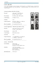
Page 90: ...y depends on oscillator of the reference clock OCXO SQ 5 10 10 OCXO MQ 2 10 10 OCXO HQ 5 10 12 OCXO DHQ 2 10 12 Rubidium 2 10 11 LED Indicators Power T1 E1 Power Init blue during initialisation green in normal operation mode T1 green selected mode T1 red output disabled yellow signal quality unknown E1 green selected mode E1 red output disabled yellow signal quality unknown LIU Power T1 E1 BITS 0 ...

Page 91: ...ns GSM CDMA UMTS DAB DVB 3 T1 4 E1 green red on off green red on off unsymm unbalanced Pinbelegung Pin assignment 1 TRING 2 TTIP LIU A 8 TRING 7 TTIP LIU E 5 TRING 4 TTIP LIU T symm balanced 1 2 4 5 7 8 There are two separate signal paths on the board LIU One is for providing the standard frequencies the second path is for generation of the telecom signals All output signals have high accuracy and...

Page 92: ...r line interface isolation isolation isolation isolation isolation isolation isolation isolation 4 096 MHz framed outputs T1 403 G703 9 balanced or unbalanced 1 544 Mbps or 2 048 Mbps diplexer diplexer diplexer amplifier amplifier amplifier amplifier clock outputs G703 13 balanced 1544 kHz or 2048 kHz clock outputs G703 13 unbalanced 1544 kHz or 2048 kHz USB IMS interface IMS M4000 Date 21st Augus...

Page 93: ...T1 or 2048 kHz E1 Four unbalanced and four balanced outputs according to ITU T G703 13 CCITT recommendation Physical electrical characteristics of hierarchical digital interfaces are available via BNC female and RJ45 connectors The framed outputs are consisting of data signals known from digital telephony which are distributed by using a special frame structure EFS Framing Mode Extended Superframe...

Page 94: ...cations The board LIU meets these recommendations T1 T 403 253 175 149 97 78 0 97 149 175 220 298 395 499 603 752 Time in nanoseconds 0 0 05 0 05 0 26 0 45 0 50 0 80 0 90 0 95 1 05 1 20 Normalized amplitude E1 G 703 269 nsec 244 nsec 194 nsec 219 nsec 488 nsec Nominal pulse 0 10 20 20 50 80 90 100 110 120 Percantage of nominal peak voltage IMS M4000 Date 21st August 2019 89 ...

Page 95: ...J45 socket 2048 kHz E1 mode or 1 544 MHz T1 mode G 703 75 Ω unbalanced BNC connector 2048 kBit s E1 mode or 1 544 MBit s T1 mode 120 Ω balanced RJ45 socket 2048 kBit s E1 mode or 1 544 MBit s T1 mode 75 Ω unbalanced BNC connector 12 8 19 6 Overview LIU Modules for IMS Systems LIU Model Size Signal bal unbal Connectors LIU A4040 8TE BITS 4 0 4 x RJ45 Clock 4 0 4 x RJ45 LIU A4004 8TE BITS 4 0 4 x RJ...

Page 96: ...lock 0 4 LIU A2020 BITS 2 0 Clock 2 0 LIU A2002 BITS 2 0 Clock 0 2 LIU_A0400 BITS 0 4 LIU A1111 BITS 1 1 Clock 1 1 Power T1 E1 LIU A4000 BITS 1 BITS 2 BITS 3 BITS 4 Power T1 E1 Clock 1 Clock 2 Clock 3 Clock 4 LIU A0040 Power T1 E1 Clock 1 Clock 2 Clock 3 Clock 4 LIU A0004 LIU Power T1 E1 A2020 BITS 1 BITS 2 Clock 1 Clock 2 LIU Power T1 E1 A2002 BITS 1 BITS 2 Clock 1 Clock 2 LIU Power T1 E1 A0400 B...

Page 97: ... 2 Mbit second It has 32 channels at the speed of 64 Kbit second 2 channels among 32 are already reserved One channel is used for signaling while the other is used for controlling The difference between T1 and E1 lies in the number of channels here Sa Bits ITU T Recommendations allow for bits Sa4 to Sa8 to be used in specific point to point applications e g transcoder equipment within national bor...

Page 98: ...from green to red In the phase locked state the output levels of the four outputs are monitored and in case of a failure signalized by an associated red LED Technical Specifications Frequency Input 10 MHz sine 1Vpp min or TTL Output Level 5 dBm 1 dBm at 50Ω Option LNO 12dB with 12 dBm output level Warm up time 3 25 C within accuracy of 1 x 10 7 Electrical Connectors BNC female Harmonics 60 dBc Pha...

Page 99: ...ked OCXO in warm up phase 10MHz reference not available Quality of the reference signal is not sufficient All LEDs green Normal operation outputs activated Associated LED red defect output or short circuit during normal operation 94 Date 21st August 2019 IMS M4000 ...

Page 100: ...to mode NC Normaly Closed If the system isn t equipped with a second clock and RSC switch unit the relay can be switched by 10MHz or PPS to monitor these signals Error Output Relay A Clock 1 Notification Events Relays Relay B Clock 2 PPS Relay C Notification Events Relay 10MHz In redundant mode the jumpers on the REL1000 are set as follows Please note The REL1000 can only be used for the IMS syste...

Page 101: ...n 1s off Normal Operation Mode St green Status A green red in case of error Clock 1 B green red in case of error Clock 2 C green red in case of error Notification Event Technical Specification ERROR Relays Switching Voltage 220 V DCmax 250 V ACmax Switching Load 60 Wmax 62 5 VAmax UL CSA 0 3 A 125 V AC 0 3 A 110 V DC 1 A 30 V DC Response Time ca 3 ms 96 Date 21st August 2019 IMS M4000 ...

Page 102: ...as the frequency itself is sent out via serial interface or is beeing converted to an analog voltage output provided by a DAC Pin Assignement 16 pin DMC Phoenix Connector Pin Signal Pin 1 A0 Pin 2 A1 Pin 3 GND Pin 4 n c Pin 5 n c Pin 6 GND Pin 7 COM 0 RxD in Pin 8 COM 0 TxD out Pin 9 Pin 14 GND Pin 15 COM 1 RxD in Pin 16 COM 1 TxD out LED Indicator LED St Init blue during inintialisation green nor...

Page 103: ...EVA FDM String STX 02049 984 CR LF 021 00 016 CR LF 022 00 378 CR LF 02315 03 30 368 CR LF 024068 15 03 30 CR LF ETX Resolution of Measurement frequency accuracy the oscillator 10MHz 100µHz time deviation accuracy of reference PPS 1ms Analog outputs 2 analog outputs for longtime recording time deviation and or frequency deviation range 2 5V 2 5V resolution 16Bit Electrical connectors 96 pin VG rai...

Page 104: ...plications The SCG Module provides four outputs with different frequencies The SCG provides a wide range of programmable word clock rates between 24Hz 12 288MHz Technical Specifications Outputs 4 x BNC 2 5V TTL into 75 Ohm outputs with configureable frequencies Input Signal 10MHz sinewave or square pulse Current Consumption 5 V 5 400 mA Ambient Temperature 0 50 C 32 122 F Humidity 85 max IMS M4000...

Page 105: ... the IO Configuration menu each output frequency can be adjusted seperately In the figure above the following value is set Frequency Out 3 Base Frequency Scale Frequency Out 3 44 1 kHz 1 4 Frequency Out 3 11 025 kHz Overview Configuration SCG U Sound Clock Generator Outputs 1 4 Output Type Studio Clock Out State Disabled Enabled Base Frequency 32kHz 44 1kHz 48kHz Scale 1 8 to 256 100 Date 21st Aug...

Page 106: ...pin female connector 4 x DARS IEC 60958 4 format resolution 24bits sampling frequency 48kHz transformer balanced Input Signals 10MHz sine wave or square pulse 1PPS Time String Power Consumption 5 V 5 400 mA Environmental Temperature 0 50 C 32 122 F Humidity max 85 Pin Assignment of the 25pin D SUB female connector DARS 1 Hot 1 Pin 18 Cold 1 Pin 6 GND 1 Pin 19 DARS 2 Hot 2 Pin 4 Cold 2 Pin 17 GND 2...

Page 107: ...m you can easily configure the Studio Clock Generator via the Web Interface Sample Configuration Output 1 In the menu IO Configuration you can set the output on DARS for every output of the M4000 The four available outputs can optionally be switched off 102 Date 21st August 2019 IMS M4000 ...

Page 108: ...es configurable video signals in different formats The generated signals have a phase reference to 1PPS Generated Signals SMPTE standards PAL Blackburst NTSC Blackburst 720p 50Hz SMPTE296M3 1080i 25Hz SMPTE274M6 720p 59 94Hz SMPTE296M1 1080i 29 97Hz SMPTE274M7 V H Frame Sync for HD and SD formats Status Info ST Status of VSG In Status of reference input A Status Out 1 2 B Status Out 3 4 Electrical...

Page 109: ...interface then Overview Configuration VSG Video Sync Generator Outputs 1 4 Output 1 Output Type Video Out Epoch TAI UTC GPS Format 720p 50Hz 1080i 25Hz 720p 59 94Hz 1080i 59 94Hz Phase Offset Offset Value Output 2 Output Type Video Out Epoch like Output 1 Format NTSC PAL Phase Offset Offset Value 104 Date 21st August 2019 IMS M4000 ...

Page 110: ...tput 4 Output Type Video Sync Out Signal Type SD H Sync SD V Sync SD Frame HD H Sync HD V Sync HD Frame HD Blank With the menu tab Misc the configuration of the VSG can be stored directly in the EEPROM of the card IMS M4000 Date 21st August 2019 105 ...

Page 111: ...which this declaration relates is in conformity with the following standards and provisions of the directives RED Richtlinie ETSI EN 303 413 V1 1 1 2017 06 RED Directive 2014 53 EU EMV Richtlinie ETSI EN 301 489 1 V1 9 2 2011 09 EMC Directive DIN EN 61000 6 2 2005 DIN EN 61000 6 3 2007 A1 2011 2014 30 EU DIN EN 55032 2012 DIN EN 55024 2010 DIN EN 61000 3 2 2014 DIN EN 61000 3 3 2013 Niederspannung...

Page 112: ......

Reviews: