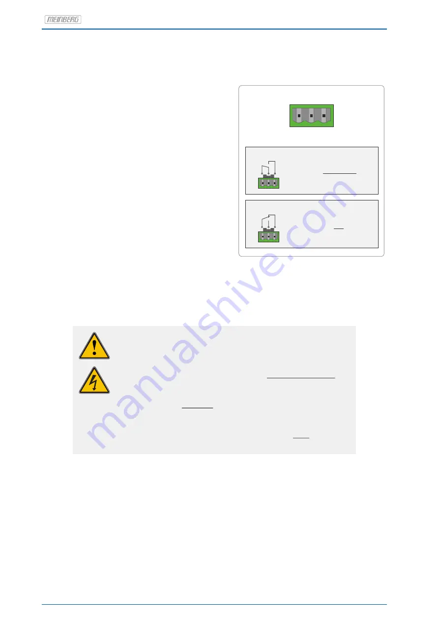
6.3 Error Relay
On the back panel of the device you can find a DFK
connector labeled "Error". This relay output is con-
nected to the TTL TIME_SYNC output of the refer-
ence clock (GPS, PZF, TCR, ...). If the internal refer-
ence clock has been synchronized by its source (GPS,
DCF77 or IRIG) the relay will switch to mode "NO".
In case of bad antenna signal or the device has been
switched off the relay falls back to mode "NC".
Technical specification
Switching voltage max.:
125 V DC
140 V AC
Switching current max.:
1 A
Switching load max.:
DC
30 W
AC
60 VA
Switching current UL/CSA:
0.46 A 140 V AC
0.46 A 65 V DC
1 A
30 V DC
Response Time:
ca. 2 ms
Normal Operation Mode
Normal Operation:
CO - NO connected
CO NO NC
Error Mode
Error:
CO - NC connected
CO NO NC
Error
CO NO NC
WARNING!
This equipment is operated at a hazardous voltage.
Danger to life due to electrical shock!
- Never work with open terminals and plugs while the power is on!
- When working on the connectors of the error relay cable,
always remove both sides of the cable from the respective devices!
Dangerous voltages can occur at the terminal of the fault signal relay!
Work on the terminal of the fault signal relay must never be carried
out with the signal voltage present!
-
22
Date: 1st March 2021
LANTIME
Summary of Contents for LANTIME M300/GPS/2LNE/AD10-AD10
Page 2: ......


