9 LTOS7 Management and Monitoring
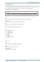
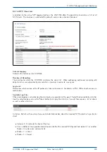
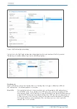
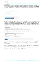
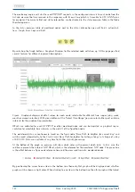
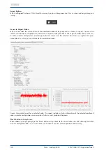
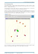
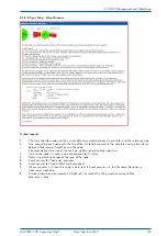
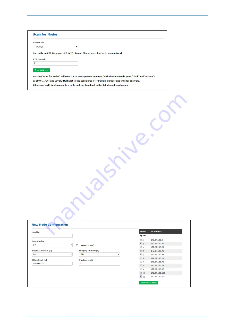
Figure: To scan the network for PTP nodes a HPS card with activated monitoring has to be selected first in
the Search for Nodes drop-down list.
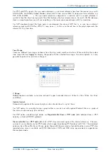
PTP Domain:
The network connected to that HPS card will be scanned in the domain, which was defined here by user. The
following mappings as defined in IEEE 1588-2008 will be scanned:
- UDP/IPv4/Ethernet,
- UDP/IPv6/Ethernet,
- Ethernet (IEEE 802.3, layer 2).
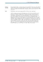
When starting the scan first a PTP Management message will be sent in broadcast mode to get the "port
state" of each PTP node - this will be done with IPv4, IPv6 and Layer2.
All PTP nodes which answer to this request will ask for the "current status" and "clock status" with man-
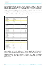
agement messages that follow. The result will be displayed as a list of all available PTP nodes. Each new
PTP Node will be entered in an overview table of the available nodes.
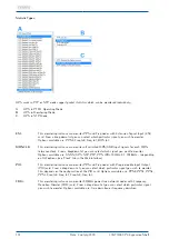
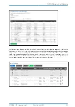
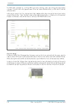
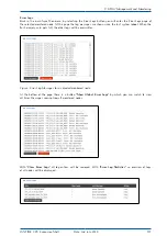
Only new nodes which have not yet been configured will be shown in the table. For each node the PTP-UUID,
MAC-Address, IP-Address, Vendor name, Feature (if a node supports PTP with extended TLV for monitoring or
PTP management messages only), Domain number, Status (the current PTP status like Slave, Master, Listen-
ing . . . ), Offset and Delay (current measured values from PTP management message) will be automatically
displayed in the table. With select-boxes new nodes can be added automatically to the list of the monitored
nodes. The parameters for Location, Group Index, Request Interval, Logging Interval, Offset Limit and Stratum
Limit can be defined in the next step before adding the selected nodes.
LANTIME CPU Expansion Shelf
Date: 2nd July 2020
121
Summary of Contents for LCES
Page 2: ......

