background image

MEITRACK T333 User Guide                                                                                                                       


Copyright ©  2015 Meitrack Group All rights reserved.                                                                                                                    - 8 - 

6.2


Charging 

When  you  use  the  T333  for  the  first  time,  connect  the  T333  GND  (-Black)  and  Power  (+Red)  wires  to  12  V  or  24  V  external 

power supply for charging. Ensure that the T333 is charged at least three hours. Eight hours are recommended. 

The T333 can be installed on a vehicle only after it is configured and tested. 

6.3


LED Indicator 

Press and hold down the power button for 3s to 5s to start the T333. 

GPS Indicator (Blue)


Steady on 

One button is pressed or one input is activated. 

Blink (every 0.1s) 

The T333 is being initialized or the battery power is low. 

Blink (0.1s on and 2.9s off) 

A GPS signal is received. 

Blink (1s on and 2s off) 

No GPS signal is received. 

3G Indicator (Green)


Steady on 

A call is coming in or a call is being made. 

Blink (every 0.1s) 

The T333 is being initialized. 

Blink (0.1s on and 2.9s off) 

A base station signal is received. 

Blink (1s on and 2s off) 

No base station signal is received. 


6.4


Configured by Computer 

This section describes how to use Meitrack Manager to configure the T333 on a computer. 

Procedure: 

1.


Install the USB-to-serial cable driver and Meitrack Manager. 

2.


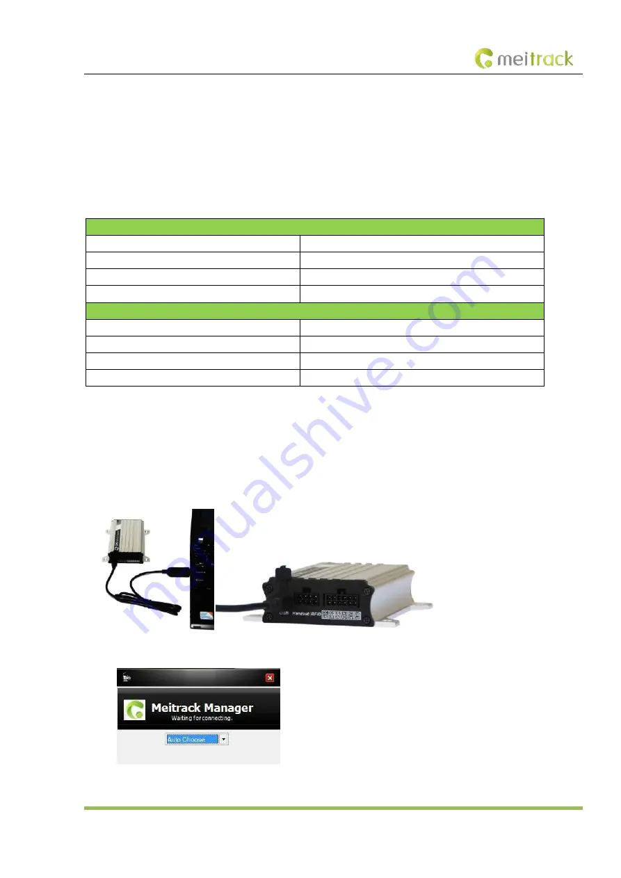
Connect the T333 to a PC by using the USB-to-serial cable. 


3.


Run Meitrack Manager, then the following dialog box will appear: 


Turn  on  the  device,  then  Meitrack  Manager  will  detect  the  device  model  automatically  and  the  parameter  page  will  appear 

Summary of Contents for iButton T333

Page 1: ...MEITRACK T333 User Guide MEITRACK T333 User Guide ...

Page 2: ...k Group All rights reserved 2 Change History File Name MEITRACK T333 User Guide Created By Owen Cheng Project T333 Creation Date Update Date 2014 06 10 2015 09 25 Subproject User Guide Total Pages 16 Version V1 3 Confidential External Documentation ...

Page 3: ...Indicator 8 6 4 Configured by Computer 8 6 5 Tracking by Mobile Phone 9 6 6 Common SMS Commands 10 6 6 1 Setting a Combined Function Phone Number A71 10 6 6 2 Setting a Listen in Phone Number A72 10 6 6 3 Setting the Smart Sleep Mode A73 11 7 MS03 Tracking System 11 8 Installing the T333 12 8 1 Installing GPS and 3G Antennas 12 8 2 Installing an I O Cable 12 8 2 1 Power Cable Ground Wire Pin 1 2 1...

Page 4: ...ss of assets and property caused by the use inability or illegality to use the product or documentation 2 Product Overview The T333 is the latest vehicle tracker supporting the 3G WCDMA network In addition to real time tracking the T333 has two way calling and remote listen in functions The T333 provides excellent and stable performance in vehicle tracking and fleet management 3 Product Function a...

Page 5: ... and remote monitoring Camera Used with a Micro SD card Take photos RFID reader Identify drivers and control vehicle starting Monitor driver attendance by RFID report LED display Display advertisements and announcements A21 LCD display Used for real time vehicle scheduling and management 3 2 Specifications Item Specifications Dimension 105 mm x 65 mm x 26 mm Weight 190g Input voltage DC 11 V to 36...

Page 6: ...vity 161 dB Positioning accuracy 10m I O port 3 digital inputs 2 negative inputs and 1 positive input 2 analog detection inputs 3 outputs 1 RS232 port 1 USB port 1 digital temperature sensor port 4 T333 and Accessories T333 and standard accessories T333 with a built in battery GPS antenna 3G antenna I O cable SOS button USB cable CD Optional accessories Camera Handset RFID reader A21 LCD display d...

Page 7: ...ations 1 Loosen the screw and remove the front cover of the T333 2 Insert the SIM card into the card slot with its gold plated contacts facing towards the Printed Circuit Board PCB 3 Close the cover and tighten the screw Note Ensure that the SIM card has sufficient balance Ensure that the phone card PIN lock has been closed properly Ensure that the SIM card in the T333 has subscribed the caller ID...

Page 8: ... or the battery power is low Blink 0 1s on and 2 9s off A GPS signal is received Blink 1s on and 2s off No GPS signal is received 3G Indicator Green Steady on A call is coming in or a call is being made Blink every 0 1s The T333 is being initialized Blink 0 1s on and 2 9s off A base station signal is received Blink 1s on and 2s off No base station signal is received 6 4 Configured by Computer This...

Page 9: ...ed SMS example Now 061314 10 36 V 26 0Km h 96 http maps meigps com lat 22 513781 lng 114 057183 The following table describes the SMS format Parameter Description Remarks Now Indicates the current location SMS header indicates the alarm type 061314 10 36 Indicates the date and time in MMDDYY hh mm format None V The GPS is invalid A Valid V Invalid 26 Indicates the 3G signal strength Value 1 32 The...

Page 10: ...ne numbers 1 2 and 3 in sequence The tracker stops dialing when a phone number responds Example 0000 A71 13811111111 13822222222 13833333333 Reply 353358017784062 A71 OK 6 6 2 Setting a Listen in Phone Number A72 SMS sending 0000 A72 Listen in phone number 1 Listen in phone number 2 SMS reply IMEI A72 OK Description When you call the tracker by using the authorized listen in phone number the track...

Page 11: ...S command to disable the sleep mode and then the tracker exits the sleep mode and returns back to the normal working mode Example 0000 A73 2 Reply 353358017784062 A73 OK For details about SMS commands see the MEITRACK SMS Protocol Note 1 The default SMS command password is 0000 You can change the password by using Meitrack Manager and SMS commands 2 The device can be configured by SMS commands wit...

Page 12: ...nsor input and negative positive input and output 1 Power 3 Input 1 5 Input 2 7 Input 3 9 Fuel sensor 11 Output 2 2 GND 4 GND 6 GND 8 AD input 1 10 Output 1 12 Digital Temperature Sensor Pin Number Color Description 1 Power Red Positive charge of the power input connected to the positive charge of the vehicle storage battery Input voltage 11 V to 36 V 12 V is recommended 2 GND Black Ground wire co...

Page 13: ...V Maximum current for output low voltage valid 400 mA Connect to an external relay to remotely cut off the vehicle fuel cable or engine power supply 11 Output 2 Yellow Output 2 Valid low level 0 V Invalid open collector Maximum voltage for output open collector invalid 40 V Maximum current for output low voltage valid 400 mA Connect to an external relay to remotely cut off the vehicle fuel cable o...

Page 14: ...ote To implement remote fuel and power cut off connect the relay to the fuel pump cable or the engine cable in series 8 2 4 Sensor Input For pin 8 analog input 1 a sensor whose output voltage ranges from 0 V to 6 6 V can be installed The analog voltage calculation formula is as follows Voltage AD x 3 3 x 2 4096 Pin 10 is connected to the A53 fuel sensor by default You can install the sensor withou...

Page 15: ...range RX T333 receiving data from the handset 4 Yellow TX T333 sends data to the handset 5 Blue Positive charge of the microphone 6 Green Negative charge of the microphone 7 Purple Positive charge of the loudspeaker 8 White Negative charge of the loudspeaker Note The RS232 port can be used with either the RFID reader or the camera at a time 8 4 Installing the RFID Reader RS232 Port Pin Number Colo...

Page 16: ...ge 5 V 2 Black Ground wire 3 Green RX T333 receives data from the camera 4 White TX T333 sends data to the camera Pin 8 connects to the T333 and pin 4 connects to the camera Connect pin 8 to the T333 Connect pin 4 to the camera Note The RS232 port can be used with either the handset or the RFID reader at a time 8 6 Mounting the T333 Tighten the four screws shown in the following figure If you have...

Reviews: