background image

Issued September 11, 2008 


OWNER’S OPERATION 

AND 

MAINTENANCE MANUAL 

OF THE 

MAK 


SPUTTERING SOURCES 


5830 Hellyer Avenue 

San Jose, CA 95138 

PH: (408) 362.1000   FX: (408) 362.1010    

E-MAIL: support@meivac.com 


YOUR S/N _____________________________ 


WARNING 


AS WITH ALL ELECTRICAL DEVICES, THERE IS A SHOCK HAZARD 
ASSOCIATED WITH THIS DEVICE.  ALL INSTRUCTIONS SHOULD BE 
FOLLOWED PERTAINING TO THE USE OF SUITABLE INTERLOCKS ON ALL 
POWER SUPPLIES TO BE USED TO POWER THIS PRODUCT.


TM 

Summary of Contents for MAK 1.3 inch

Page 1: ...138 PH 408 362 1000 FX 408 362 1010 E MAIL support meivac com YOUR S N _____________________________ WARNING AS WITH ALL ELECTRICAL DEVICES THERE IS A SHOCK HAZARD ASSOCIATED WITH THIS DEVICE ALL INST...

Page 2: ...AMOUNT MUST BE APPLIED A GLOVED FINGER USED TO SPREAD EVENLY OVER THE CATHODE BLOCK The block should be clearly visible thru a thin gray film NOTE A substitute paste such as thin 0 005 Indium foil can...

Page 3: ...meters 14 PURITY 14 SURFACE 14 TARGET DIMENSIONS 14 TARGET SUPPLIERS 14 MACHINABLE MATERIALS 15 NON MACHINABLE MATERIALS 16 Target Mounting 16 Rate vs Power 18 Relative Sputtering Rates of 50 Material...

Page 4: ...shipment throughout the world INTRODUCING MAK SPUTTER SOURCES The MAK sputter sources were designed developed tested under controlled laboratory condi tions at a major United States government labora...

Page 5: ...r are re turned to the cathode by collision with gas molecules The ensuing process might be compared to a fine sand blasting in which the momentum of the bombarding particles is more important than th...

Page 6: ...as a commercial process Several magnetic configurations were used such as the post cathode magnetically enhanced hol low cathodes and magnetrons In order to make a magnetron work it is necessary to c...

Page 7: ...This meant high voltage with current draw being limited by the gas pressure Typical voltages were 3 5 kV with a current from 50 250 ma at pressures of 50 250 microns R F power was introduced be cause...

Page 8: ...ith suitable gauging to measure and monitor pressures in the 0 5 600 micron range during sputtering and the 1x10 5 to 1x10 9 torr range during pre sputter pump down The system must also be equipped wi...

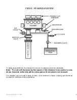
Page 9: ...e will decrease by the square of the distance from source to sub strate however uniformity will be enhanced as this distance is increased The chamber may be made of glass or metal If the chamber is me...

Page 10: ...the end of the tube 2 Pull straight out on the electrical connector mounting assembly The whole assembly will come off leaving the water tubes free and the electrical connector assembly unplugged fro...

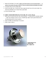
Page 11: ...See technical specifications for minimum flow requirements 10 Connect the power cable B DIRECT FLANGE MOUNTING VIA CF ISO ANSI JIS and other flanges 1 MAK Source has been attached to the mounting flan...

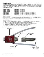
Page 12: ...ork P N SU R1001 1000 Watt RF Generator and Automatic Tuning Network DC Connection The power supply is provided with twelve feet of RG 8 U high voltage cable Connect the PL 259 connector to the power...

Page 13: ...UTTERING CAUTIONS IN RF HOOK UP Cable length between should be a derivative of the 13 56 MHz Wave length Approximately 48 24 or 12 feet and be 50 ohm RF shielded cable Cable length between the tuning...

Page 14: ...3 0 MAK 4 0 MAK 6 0 MAK Target Suppliers For a list of qualified target suppliers see Appendix B Simplicity in Sputtering INTRODUCING The MAK Planar Magnetron Sputtering Source TARGET KEEPER Target In...

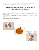
Page 15: ...MAK MACHINABLE MATERIALS By attaching a magnetic keeper to the target the MAK source uses the magnetics of the gun to hold the target in place If you have old targets NO PROBLEM Drill and tap your exi...

Page 16: ...tapped hole Backing Plates Ceramics oxides and any other non ma chinable targets are commonly bonded to a copper backing plate for all sputtering sources MAK Backing Plates The MAK sputter source use...

Page 17: ...Spread a small amount of thermal contact paste on the top of the copper chill block The paste should be spread evenly and so thin you can see through it a If the thermal contact paste is not used a t...

Page 18: ...onvenient and readily available material to use as a reference Once the rate of copper is known then the other 49 may be approximated Please Note These rates may vary from those of other periodicals d...

Page 19: ...is to correlate the values taken with the rate monitor with those taken by step sample method If the distance from the substrate to the target is changed and the power remains constant the change in d...

Page 20: ...return any defective units prepaying the freight costs and ensuring that the units are returned to the location identified by MeiVac on the RMA Provided the work required on the unit is covered under...

Page 21: ...00 0 080 0 437 Target Volume max ccm cu inch 4 90 0 30 19 25 1 17 72 47 4 42 154 00 9 40 463 00 28 25 Target Surface Area cm sq sq in 8 56 1 33 20 27 3 14 45 60 7 07 81 10 12 56 182 4 28 25 ELECTRICAL...

Page 22: ...D MECHANICAL Max OD mm inch 59 70 2 350 59 70 2 350 85 80 3 378 104 80 4 125 170 80 6 725 Smallest Mounting Flange CF ISO 4 1 2 DN63 NW 63 4 1 2 DN 63 NW 63 6 DN 100 NW 100 6 3 4 DN125 NW 160 10 DN200...

Page 23: ...m Tico Titanium 52900 Grand river New Hudson MI 48165 Mr J P Cruzen PH 800 521 4392 FX 248 446 1995 www ticotitanium com Process Materials Inc 5625 Brisa Street Suite A Livermore CA 94550 Steve Verley...

Page 24: ......

Page 25: ......

Page 26: ......

Page 27: ......

Page 28: ......

Page 29: ......

Page 30: ......

Page 31: ......

Page 32: ......

Page 33: ......

Page 34: ......

Page 35: ......

Page 36: ......

Page 37: ......

Page 38: ......

Page 39: ......

Page 40: ......

Page 41: ......

Page 42: ......

Page 43: ......

Page 44: ...g Magnet L130 09 Stainless Steel Ground Shield L130A14 Block Assembly J1200 06 Center Magnet J1200 33 O Ring J1200 34M Metal Seals J1234 30 Water Lines 2 w ferrules LL 130 01 Keeper w hole screw pkg 1...

Page 45: ...00 10 Aluminum Ground Shield L200A14 Block Assembly J1200 06 Center Magnet J1200 33 O Ring J1200 34M Metal Seals J1234 30 Water Lines 2 w ferrules LL 200 01 Keeper w hole screw pkg 10 MAK 200 BP Coppe...

Page 46: ...ONLY L300 10NT Aluminum Ground Shield L300 13 Center Magnet L300 24 Ring Magnet L300A14 Block Assembly J3400 33 O Ring J3400 34M Metal Seals J1234 30 Water Lines 2 w ferrules LL 300 01 Keeper w hole...

Page 47: ...net Assembly L400A14 Block Assembly J4600 13 Center Magnet J4600 32 Ring Magnet Segment 10 31 25 each J3400 33 O Ring J3400 34M Metal Seals J1234 30 Water Lines 2 w ferrules LL 400 01 Keeper w hole sc...

Page 48: ...t Plug L600 41 O Ring L600A14 Block Assembly L600A20 Center Magnet Assembly J4600 13 Center Magnet J4600 32 Ring Magnet Segments 16 31 25 each L600 42 Water Lines 2 w ferrules LL 600 01 Keeper w hole...

Page 49: ...g cooling all components except small cathode area are at ground or neutral potential Cathode Cooling Block Magnet Return AlN Water Line Power Feedthru Water Line Passage for Insulated Power Post Cool...

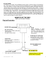
Page 50: ...voltage for comparable power levels Standard MAK sputters magnetic material Balanced Unbalanced Magnet array is INTERCHANGEABLE from balanced or unbalanced Disassembly of source NOT REQUIRED BENEFITS...

Page 51: ...tor permits RF DC operation One Vacuum Seal Elastomer HV or Metal UHV field interchangeable No water to Vacuum Seal No Mechanical Target Clamp Target surface is not in contact with dissimilar clamping...

Page 52: ...1 Simplicity in Sputtering INTRODUCING Planar Magnetron Sputtering Source The MAK...

Page 53: ...2 Simplicity in Sputtering Target Installation on the MAK Target Keeper Cathode Magnets...

Page 54: ...mounted by attraction of the center magnet No mechanical clamping of the target THUS Ease of target change Adjustable anode THUS Allows for target thickness variations Prevents material build up Stan...

Page 55: ...4 Simplicity in Sputtering MAK without target installed Target Keeper Cathode Adjustable Anode...

Page 56: ...5 Simplicity in Sputtering MAK with target installed Target mounted with magnetic keeper Anode retracted...

Page 57: ...6 Simplicity in Sputtering The MAK with target and anode Anode adjusted to accommodate thicker target Target Slotted anode allows for variable target thickness...

Page 58: ...7 Simplicity in Sputtering MAK target installed w o anode Target 0 100 gap between target and magnets Magnet segments...

Page 59: ...to a copper backing plate for all sputtering sources MAK Backing Plates The MAK sputter source uses the same backing plate but with a magnetic keeper attached The keeper holds the target in place with...

Page 60: ...et Example This is an example of a SiO2 target bonded to a copper backing plate with a magnetic keeper attached target keeper bond copper backing plate TARGET MOUNTING OF THE MAK NON MACHINABLE MATERI...

Page 61: ...ou have old targets NO PROBLEM Drill and tap your existing targets as shown and attach the metallic keeper Then snap the target into place It s that simple TARGET MOUNTING OF THE MAK MACHINABLE MATERI...

Reviews: