M2D-Laser-Scanner with Ethernet-Interface
Manual
HB-M2D-Ethernet-E
Page 9 of 39
www.MElsensor.com
P
P
o
o
w
w
e
e
r
r
a
a
n
n
d
d
s
s
i
i
g
g
n
n
a
a
l
l
c
c
o
o
n
n
n
n
e
e
c
c
t
t
o
o
r
r
D
D
-
-
S
S
u
u
b
b
-
-
2
2
5
5
p
p
i
i
n
n
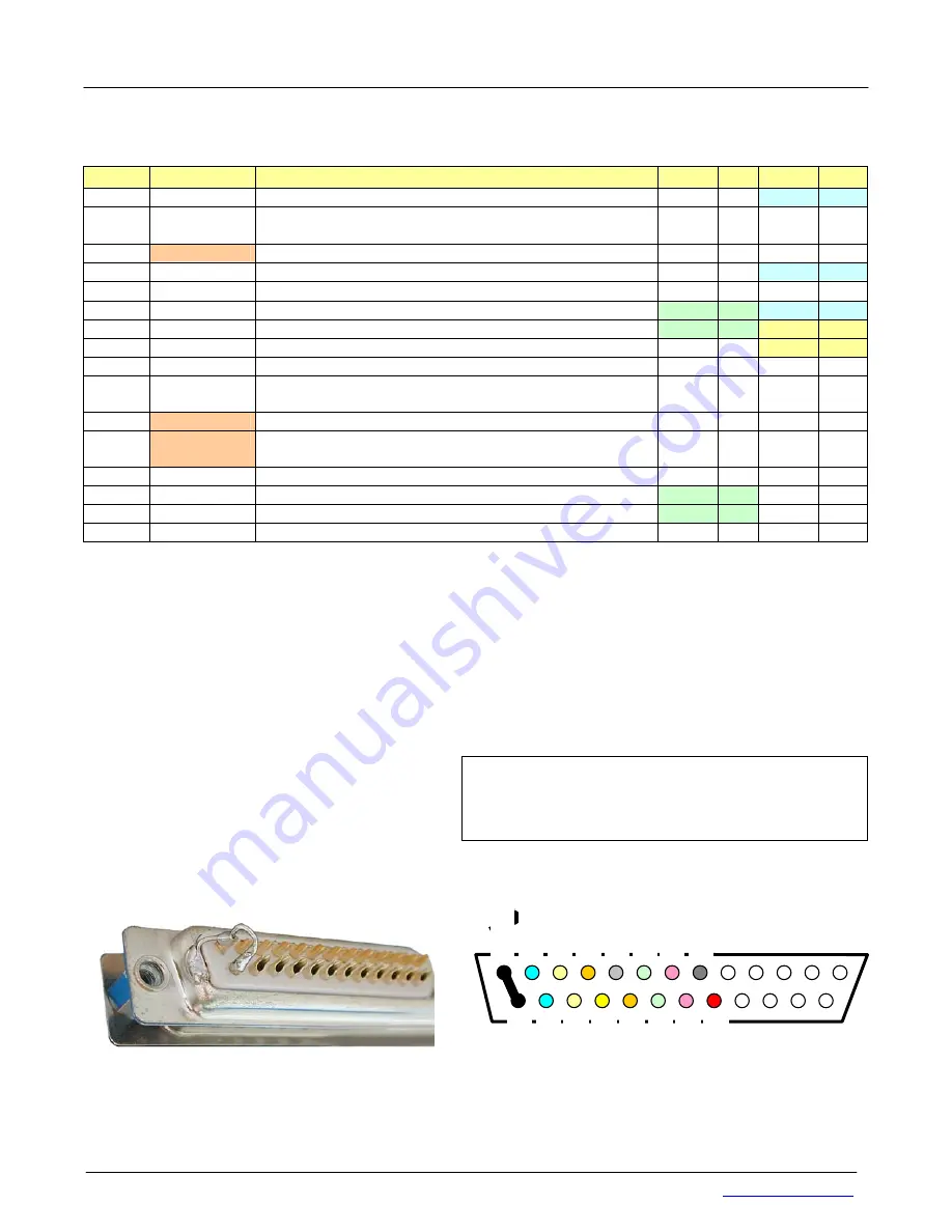
----------------------------Sensor-------------------------------------------------------------------------PC----------------------------------
D-Sub 25
RJ45-Ethernet RS-232
Pin
Signal
Meaning / signal level
Func. Pin Func. Pin
1 Gnd
Ground
Br. 1
1
2
Sync out
Sync out from the Master is connected to Sync-in
of the Slaves.
3
TxD_PROG
Send data RS-232 for Firmware-update *
TX 2
4
Din 1
Digital input 1
Br. 1
4
5 RIP
Reset IP Address
→
connect to ground = default IP * *
6
Tx-
Transmit Data - Ethernet
Rx -
6
Br. 1
6
7
Rx-
Receive Data - Ethernet
Tx -
2
Br. 2
7
8
Case
PE ; ground ***
Br. 2
8
14
Gnd
Ground, 0 V DC
GND 5
15
Sync in
Sync in from Master, TTL ... 24 V Logic 0/1 leading edge
triggers ext. Trigger mode must be set in register 0x14 !
16
RxD_PROG Receive data RS-232 for Firmware-update *
RX 3
17
CPU_PROG Programming control for Firmware-update
For update connect to + Ub over a 3.000 Ohms resistor*
18
Din 2
Digital input 2
19
Tx+
Transmit Data + Ethernet
Rx +
3
20
Rx+
Receive Data + Ethernet
Tx +
1
21
+ Ub
10 ... 30 V DC , approx. 5.3 W
Sync in = ext. Trigger
Sync input has internal pull-down resistor.
* using firmware update is on customers risk (no warranty).
** connect RIP-Pin (Pin 5 to ground). Then cycle power. After restart, the Scanner will communicate on the default
IP address. Set new IP address using MEL-Demo-Software Rev.2.0.4.2, Tab 11. Release RIP-Pin from ground.
Cycle power. Now the new IP-address is active. For alternative method see also page 24.
*** ground should be applied in a central place at machine side. Avoid ground loops, connect ground leads in a
“star” structure. Connect protective ground in central place to the machine, connect the case with short leads.
Bridges for simulated RS-232 hardware handshake
Bridge 1: pins 1 – 4 -6
Bridge 2: 7 – 8 Connect Case of D-Sub-9Pin connector to Pin 5 (GND).
G
G
r
r
o
o
u
u
n
n
d
d
c
c
o
o
n
n
n
n
e
e
c
c
t
t
i
i
o
o
n
n
;
;
c
c
o
o
n
n
n
n
e
e
c
c
t
t
o
o
r
r
D
D
-
-
S
S
u
u
b
b
-
-
2
2
5
5
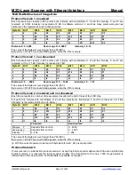
The enclosure of the D-Sub connector is wired with a
short lead to bridge 1-14. The Ethernet cable shield is
connected with a short lead to the bridge 1-14.
Pin 8 is not connected.
connect Pin 1 to Pin 14 as a bridge,
then connect here
o
Supply negative ( 0 V)
o
Connector enclosure
o
Ethernet cable Shield
4 Digital In 1
3 TxD Pro
g
2 Sync-Out
5 Reset IP
1 GND
8 case
7 Rx-
6 Tx-
Rx+ 20
+Ub 21
Tx+ 19
Digital In 2
18
RxD_
Prog 16
CPU_
Prog
17
Sync-In 15
GND 14


