150 of 271
5. Loosen the two nuts on the left side at the end of the long bolts as shown in Figure 3 above.
Figure 4 - Thread Feeder Assembly, Right Thread
6. Remove the two socket head screws on the right side as shown in Figure 4 above.
7. Remove the assembly with the 16 thread feeders to the right side as one unit. Do not disassemble
the assembly any further.
•
IMPORTANT! Do not disassemble the 16 needle thread feeder assembly. Disassembly and
reassembly of this component requires specific skills and alignments that are best done at the
factory.
8. Turn the machine on and Color change to needle number 1.
9. Slide the replacement thread feeder assembly onto the needle case.
10. Replace and tighten the two bolts on the right side as shown in Figure 4 above. Tighten the bolts
only enough to secure the bracket to the needle case.
11. Install the nuts on the left bracket and tighten them just enough to hold the left bracket in place.
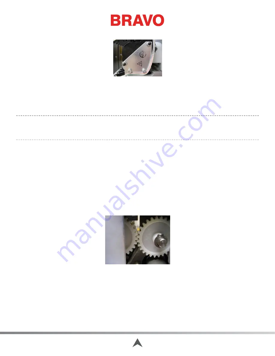
12. Adjust the thread feeder assembly so that the thread feeder gear meshes with the gear on the
Color Change, Take-Up Feeder Housing Assembly. See Figure 5. The maximum gap between the
gears should be no more than.032” [0.81mm]. Gage Pin (PN: 32996) should not go between the
two gears. See Figure 6.
Figure 5 - Thread Feeder Gears
Table of Contents


