175 of 271
rear section and from the main PCB at connector location J1. You also need to remove the radio
interference ferrite.
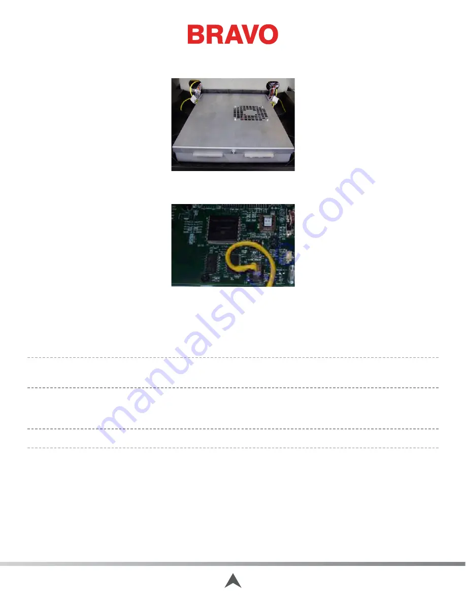
Figure 2 - EMI Cover over Main Board
4. Remove the EMI cover from the main control board.
Figure 3 - Ethernet Connector Location on Main PCB (J1)
5. Remove the old Ethernet harness.
6. Connect the replacement harness to the main PCB at connector location J1.
7. Replace the EMI cover carefully.
•
Note: Make sure that you replace radio interference ferrite exactly as shown in the instructions
for the appropriate EMI cover.
8. Connect the other end of the Ethernet harness to the back of the Ethernet coupler on the power
input assembly plate and coil any excess length in back of the coupler as shown in Figure 1.
•
Note: Make sure that you replace radio interference ferrite exactly as shown in Figure 1.
9. Replace the twist-lock cable ties on the harness tieing it to adjacent ones.
10.
Reinstall the rear covers and tighten the screws to the torque specifications.
11. Turn the machine on and load the Bravo OS.
12. If the software shows the machine being connected, the Ethernet harness and the circuitry on the
main PCB is working correctly.
Table of Contents


