105 of 271
Color Change, Take-Up, Feeder Housing Assembly
The Color Change/Take-Up/Feeder Assembly is a sensitive component that should be repaired carefully
following the procedures contained for each individual component. When repairing components on this
assembly, do not loosen the screws that mount the housing to the upper arm body.
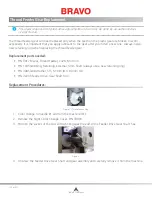
Figure 1 - Color Change/Take-Up/Feeder Housing Assembly
Do not attempt to repair or replace any component on the Color Change/Take-Up/Feeder Assembly ex-
cept as provided by the below procedures:
• Color Change Linear Actuator Replacement
• Thread Feeder Gear Replacement
• Thread Feeder Optical Sensor Replacement
• Thread Feeder Radial Bearing Replacement
• Thread Feeder Stepper Motor Assembly Replacement
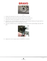
Figure 2 - Take-Up Lever Drive Gear Assembly
CAUTION!!
Do not attempt to do any repairs or adjustment to the take-up lever drive gear, tor-
sion spring or shaft. These components require a special fixture and specific training to adjust
properly. If this component is tampered with, the entire Color Change/Take-Up/Feeder Assembly
will have to be replaced.
Replacement Procedure for Entire Color Change/Take-Up/Feeder Assembly:
1. Color change to needle 1.
2. Remove the needlecase assembly.
3. Disconnect the motor and PCB harnesses.
4. Use a marking pen and trace the outline of the base of the Color Change/Take-Up/Feeder
Assembly on the upper arm body.
Table of Contents


