51 of 271
32.
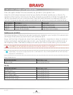
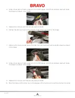
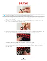
With a small flat blade screwdriver, carefully move and hold the grabber connecting lever over to
the left as shown in the image.
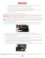
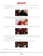
33. Using the grease applicator, apply a small amount of HP grease onto the grabber eccentric surface
between the grabber connecting lever and the grabber home flag as shown in the image.
•
IMPORTANT:
Ensure that no grease is applied to the black grabber flag on the right side.
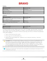
34. Once the grease has been applied, release the grabber connecting lever and remove the small
screwdriver.
This completes the monthly maintenance procedure
Quarterly Maintenance
Take-Up Lever Cam, Presser Foot Cam Follower, & Right Needle Bar Guide
WARNING!!
If you currently have a hoop or clamping system on the machine, please remove it.
Failure to fully remove a clamping system can result in damage to the machine. When you click
on the next button, the machine will move to the appropriate position.
1. Color change to needle #1.
2. Move the x-beam all the way back.
3. In the software, go to “Tools>Maintenance> Head Timing Tab” and got to “Bottom Center”.
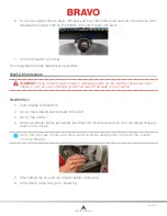
4.
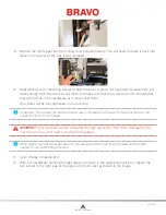
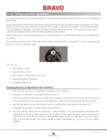
Using a 3mm and a 2.5mm Allen wrench, loosen and remove the five (5) screws shown in the
image.
Table of Contents


