


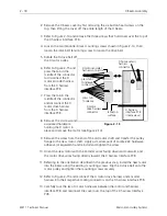
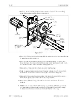
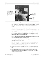

5. Grasp the Ethernet PCB at the top corners and gently rock it out of its connectors
in the backplane PCB. Remove the Ethernet PCB.
6. Replace the Ethernet PCB by reversing the previous steps.
7. Install the screw and washer at the card edge mounting bracket to secure the
printed circuit board.
8. Reinstall the Ethernet cable to the end of the Ethernet PCB.
9. Remove the static grounding strap and replace the card cage cover.
10. Reinstall the right rear table top.
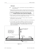
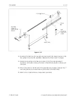
Interface PCB
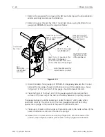
The Interface PCB is positioned inside the card cage between the Ethernet PCB and
the Low Voltage Driver PCB as shown in Figure 2-11. Refer to the following
procedure for replacing the Interface PCB.
1. Turn OFF the power switch to the EMT 1.
2. Remove the card cage cover and install a static grounding strap between the
working surface and the personnel performing this procedure.
3. Grasp the Interface PCB at the top corners and gently rock it out of its
connectors in the backplane PCB. Remove the Interface PCB.
4. Replace the Interface PCB by reversing the previous steps.
5. Remove the static grounding strap and replace the card cage cover.
6. Reinstall the right rear table top.
Low Voltage Driver PCB
The Low Voltage Driver PCB is positioned inside the peripheral card cage between
the Interface PCB and the XYZ Motor Driver Amplifier PCB (see Figure 2-11). Refer
to the following procedure for replacement.
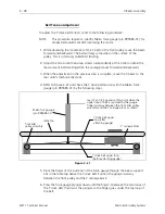
1. Turn OFF the power switch to the EMT 1.
2. Remove the card cage cover and install a static grounding strap between the
working surface and the personnel performing this procedure.
3. Grasp the Low Voltage Driver PCB at the top corners and gently rock it out of its
connectors in the Backplane PCB. Remove the Low Voltage Driver PCB.
4. Replace the Low Voltage Driver PCB by reversing the previous steps.
2 - 14
Electronics Section
EMT 1 Technical Manual
Melco Embroidery Systems


