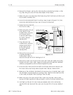
2. Remove the X beam cover by first removing the six button head screws on the
top, then lifting the cover off the entire length of the X beam.
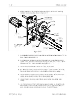
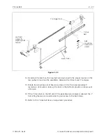
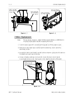
3. Refer to Figure 2-14 and remove the three screws that hold cover over the top of
the X harness interface PCB.
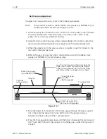
4. Loosen the two tensioner block mounting screws shown in Figure 2-14, then
loosen the drive belt tensioning screw to loosen the drive belt.
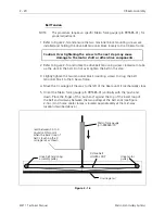
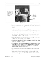
5. Rotate the X drive belt off
the X motor pulley.
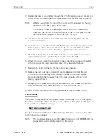
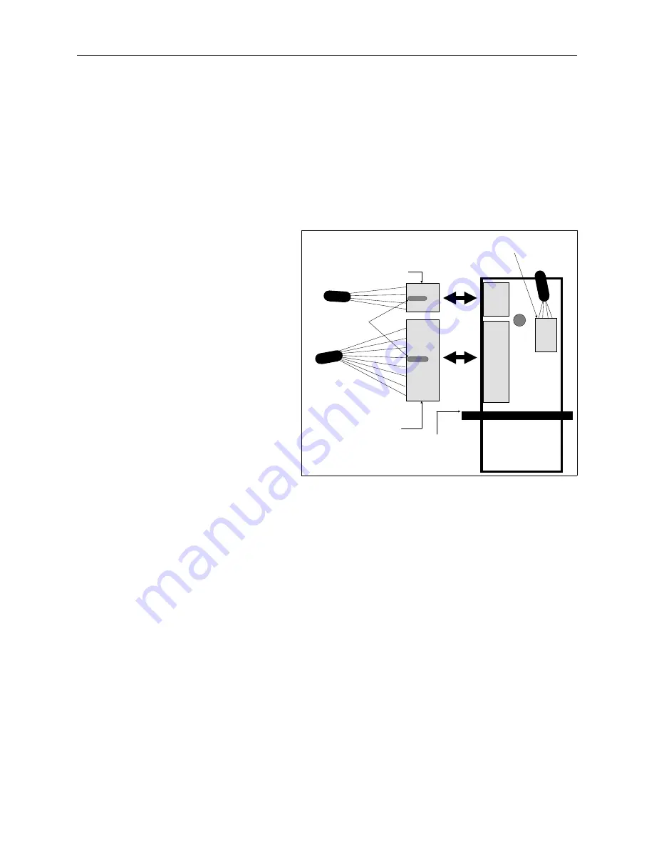
6. Refer to Figure 2-15 and
press the tab in the
middle of the connector
to disconnect the X
motor encoder harness
from the X harness
interface PCB.
7. Press the tab in the
middle of the connector
and disconnect the X
motor drive harness
from the X harness
interface PCB.
8. Remove the 4 screws and
associated hardware
holding the X motor in
place and remove the motor (see Figure 2-14).
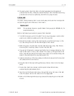
9. Remove the screw from the end of the old motor shaft and transfer the pulley
flange to the new motor shaft. Apply a small amount of Loctite 222 hardware
adhesive (or equivalent) and reinstall and tighten the screw.
10. Orient the new motor with the encoder wires facing down and outward, and
the motor drive wires facing directly toward the X harness interface PCB.
11. Referring to the orientation described in the previous step, install the new motor
into the beam using the existing mounting screws. Slip the X drive belt onto the
motor pulley and tighten the mounting screws securely.
12. Refer to Figure 2-15 and reconnect the X motor drive harness and encoder
harness into their respective mating connectors on the X harness interface PCB.
13. Carefully tuck the two X motor harnesses between the motor and harness
interface PCB and reconnect the cover over the top of the X harness interface
PCB.
X motor
drive harness
connector
press tab
to release
X harness
interface PCB
(inside view)
table top
surface
X motor encoder
harness connector
press tabs
to release
connectors
X home sensor
harness
connector
Figure 2 - 15
2 - 18
X Beam Assembly
EMT 1 Technical Manual
Melco Embroidery Systems


