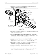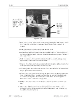
14. If replacing the X drive belt, refer to the belt replacement and adjustment
procedure at this time, otherwise proceed directly to the X drive belt tensioning
procedure for instructions tightening the belt to the proper tension.
X Drive Belt
This belt is directly driven by the X motor shaft pulley and moves the X carriage left
and right along the rail in the base of the X beam.
Replacement
NOTE:
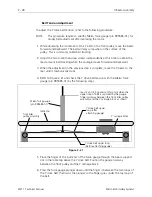
This procedure requires a specific Melco force gauge (p/n 995585-01), for
proper adjustment.
Refer to the following procedure to replace the X drive belt:
1. Turn OFF the power switch to the EMT 1 and remove the power cord from the
power source electrical outlet and the rear of the machine.
2. Remove the X beam cover by first removing the six button head screws on the
top, then lifting the cover off the entire length of the X beam.
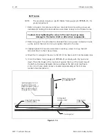
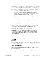
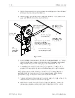
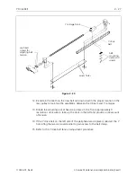
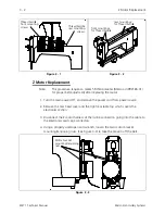
3. Refer to Figure 2-14 and loosen the drive belt tensioning screw, then the two
tensioner block mounting screws to loosen the drive belt.
4. The existing X drive belt is clamped and held to the X carriage plate by two flat
head socket screws, a clamp, and a spacer. The screws go through holes in the
belt as well. Remove the two flat head socket screws and associated clamp and
spacer to free the belt at this area (see Figure 2-14).
5. Slide the old belt out of the two pulleys at either end and position the new belt
into place where the old one was.
6. Bring the ends of the new belt together above the two holes in the X carriage
plate.
7. Position the X belt clamp above, and the spacer below the belt ends,
sandwiching the belt between them.
8. Insert the two flat head socket screws through the clamp, the holes in the belt
ends, the spacer, and into the holes in the X carriage plate.
9. Refer to the following belt tensioning procedure for adjusting the X drive belt
tension.
X Drive Belt
2 - 19
110344-01, Rev B
2. Service Maintenance (except embroidery head )


