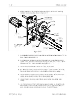
1. Refer to the procedure for removing the left rear table top (with optional bobbin
winder assembly) and remove the table top.
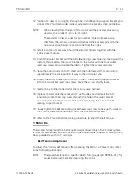
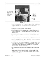
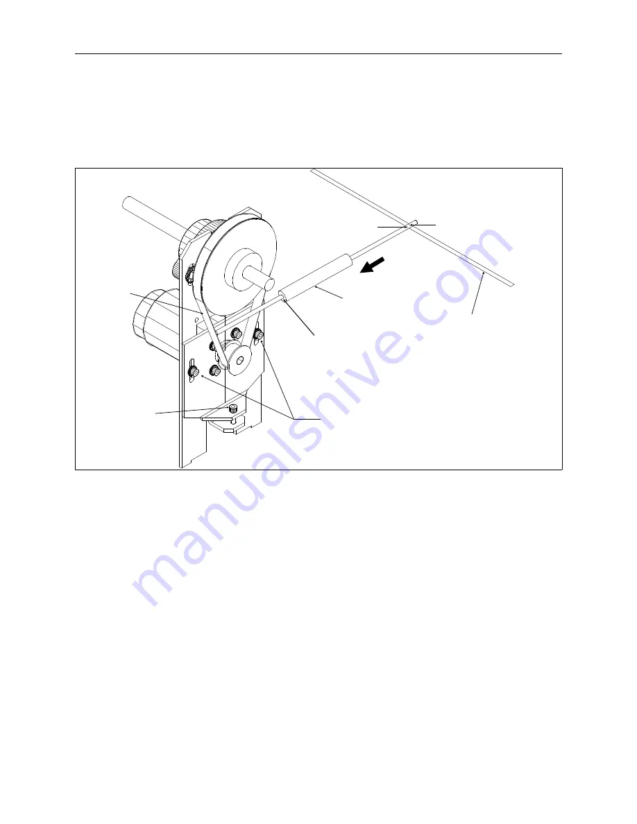
2. Refer to Figure 2-18 and check the Y motor belt tension using the Melco force
gauge (p/n 995585-01) and the steps that follow:
3. Orient the Melco force gauge (p/n 995585-01) diagonally between the Y motor
belt and the top edge of power distribution section of the peripheral as shown
in Figure 2-18. The ’push end’ of the gauge should be toward the belt.
4. Place the finger of the ’push end’ of the gauge against the inside (toothed
surface) of the rear loop of the belt and mid-way between the pulleys centers.
The gauge plunger should be located just under the large Y shaft pulley when
positioned correctly. The other end of the force gauge plunger will be resting
against the top edge of front wall of the power distribution section.
5. Place a pencil mark on the plunger at the location where the inside surface of the
power distribution section wall touches the plunger.
6. Measure 0.2 inch toward the end of the plunger from the mark made in the
previous step and place another pencil mark on the plunger at that location.
top edge of power
distribution section
of the peripheral
belt
tensioning
socket head
cap screw
make first pencil mark
here at inside surface
of wall edge
make second pencil
mark here (0.2" from
first pencil mark)
read 10 +/- 2.0 pounds at this
point when the gauge is
positioned at the second mark
on the other end of the plunger.
Melco force gauge
(p/n 995585-01)
Y motor belt
(rear loop)
motor bracket securing
socket head cap screws
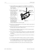
Figure 2 - 18
2 - 24
X Beam Assembly
EMT 1 Technical Manual
Melco Embroidery Systems


