

12. Be certain the teeth on the new belt are positioned in the proper location in the
rear pulley to maintain the parallelism between the X beam and Y carriages.
13. Rotate the adjusting socket head cap screws in the front approximately 3
revolutions clockwise to take up the slack in the belt and provide some amount
of tension.
14. If the Y drive belt on the left side of the peripheral was replaced, reinstall the Y
home flag that was removed earlier to gain access to the belt clamp.
15. Refer to the Y drive belt tension adjustment procedure.
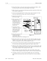
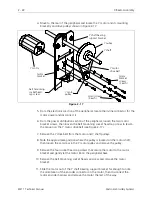
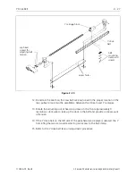
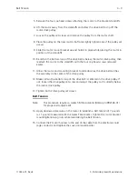
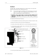
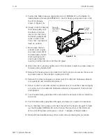
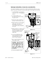
Y carriage block
belt
mounting
clamp and
screws
cap head
screws for
adjusting belt
tension
access holes
Y drive
belt
Figure 2 - 20
Y Drive Belt
2 - 27
110344-01, Rev B
2. Service Maintenance (except embroidery head )