
Belt Tension Adjustment
To adjust the Y drive belt tension, refer to the following procedure:
NOTE:
This procedure requires a specific Melco force gauge (p/n 995585-01), for
proper belt adjustment after replacing the motor.
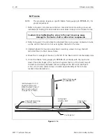
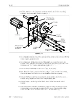
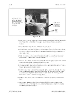
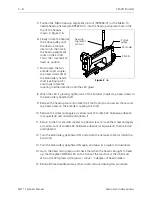
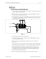
1. While observing the movement of the Y belt on the front pulley, move the beam
forward and backward. The belt will vary somewhat on the surface of the
pulley. This is commonly called belt tracking.
2. Adjust the two socket head cap screws independently at this time to obtain the
least amount belt tracking when the carriage moves forward and backward.
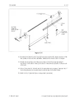
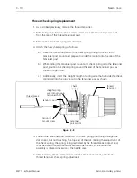
3. When the adjustment in the previous step is complete, move the X beam to the
rear until it mechanically stops.
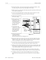
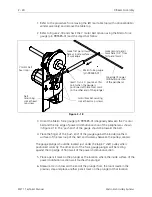
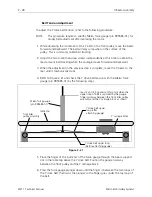
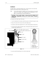
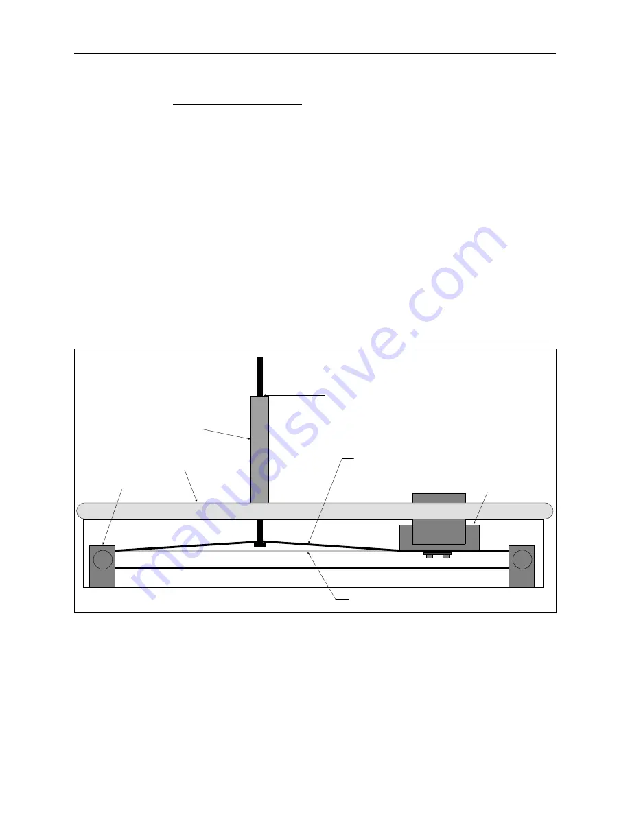
4. Refer to Figure 2-21 and check the Y drive belt tension with the Melco force
gauge (p/n 995585-01) by the following steps.
5. Place the finger of the ’pull end’ of the force gauge through the beam support
slot in the table top above the Y drive belt. Position the gauge mid-way
between the front pulley and the Y carriage block.
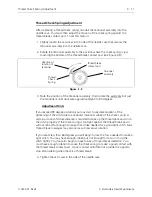
6. Press the force gauge plunger down until the finger is between the two loops of
the Y drive belt, then twist the plunger so the finger goes under the top loop of
the belt.
read 2 +/- 0.25 pounds at this point when the
upper loop of belt is captured by the gauge
finger mid-way between the front idler pulley
assembly and the Y carriage block as shown
Melco force gauge
(p/n 995585-01)
front idler
pulley assembly
Y drive belt upper
loop (after
attaching gauge)
Y drive belt upper loop
(before attaching gauge)
Y carriage block
table top
Figure 2 - 21
2 - 28
X Beam Assembly
EMT 1 Technical Manual
Melco Embroidery Systems