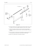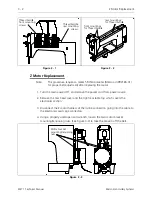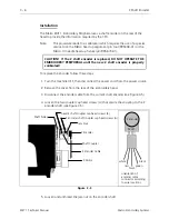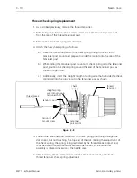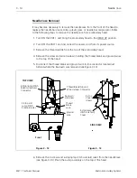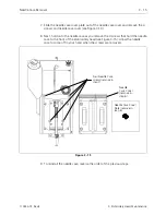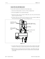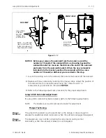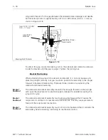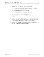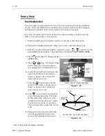
6. Pull the encoder out of the shaft coupling and encoder mount. Capture the jam
nut and washer as the encoder shaft is removed.
7. Insert the new encoder/shaft into the hole of the encoder mount, place the
washer and then the jam nut onto the encoder shaft as you insert the shaft
through the mounting plate.
8. Insert the encoder shaft into the shaft coupling.
9. Tighten the jam nut, then snug the coupling cap head screws onto the encoder
shaft.
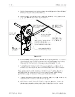
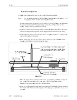
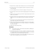
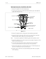
10. Orient the connector on the encoder cable so the outside black wire is to the
right and will plug into pin 1 of the new encoder (see inset in Figure 3-5). Push
the encoder cable connector onto the new encoder.
CAUTION! If the Z shaft encoder is replaced, DO NOT OPERATE THE
EMBROIDERY PERIPHERAL until the new Z shaft encoder is properly
calibrated!
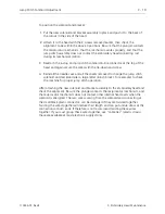
11. Calibrate the Z encoder per the following procedure.
Calibration
CAUTION! Failure to properly calibrate the Z shaft encoder after
replacing it, may cause damage when attempting to operate the
machine.
Note:
This procedure leads to a calibration which requires the use of a special
service tool: the Melco head up alignment pin tool (995338-01) or the
Melco 10 needle head up fixture (p/n 995673-01).
1. Install the Z shaft encoder as described previously.
Note: To perform this procedure, it is important that the peripheral does
not "download." To insure this condition remove the network cable (or
boot disk if being used).
2. With the network cable removed (or boot disk not inserted into the disk drive),
turn ON the embroidery peripheral.
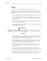
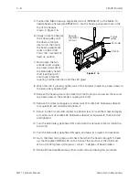
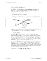
3. Locate the green LED marked "ZINDEX" on the front of the peripheral, above the
lowered table top (see Figure 3-4). Or with the card cage cover removed, locate
the innermost LED on the top of the CPU.
4. Remove the thread saddle to access the head alignment hole in the next step.
Calibration
3 - 7
110344-01, Rev B
3. Embroidery Head Maintenance

