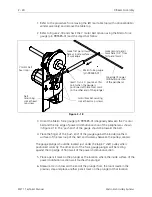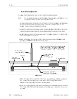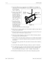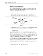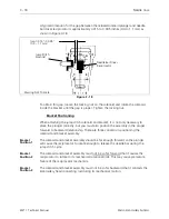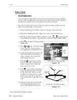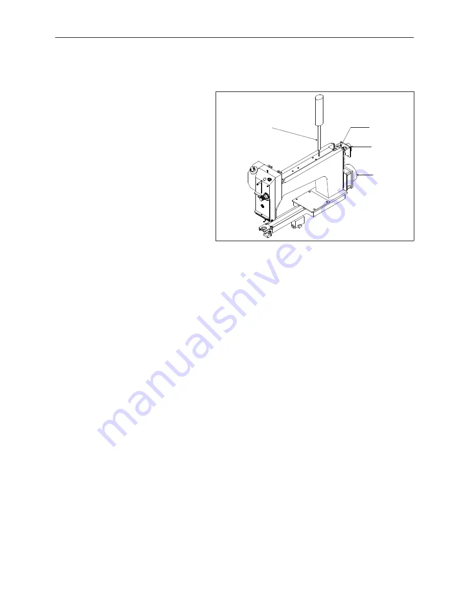
5. Position the Melco head up alignment pin tool (995338-01) or the Melco 10
needle head up fixture (p/n 995673-01) into the head up alignment hole in the
top of the head as
shown in Figure 3-6.
6. Slowly rotate the head at
the Z drive pulley until
the head up tool pin
inserts into the hole in
the head up alignment
collar on the Z shaft.
This is the "mechanical"
head up position.
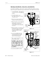
7. Now loosen the two
encoder shaft coupler
cap head screws (B) at
the embroidery head Z
shaft (see Figure 3-5)
and slowly rotate the
coupling in either direction until the LED glows.
8. When the LED is glowing, tighten one of the encoder coupler cap head screws to
the embroidery head Z shaft.
9. Remove the head up tool and rotate the Z shaft until you can access the second
cap head screw on the encoder coupling to Z shaft.
10. Remove the screw and apply a small amount of Loctite 222 hardware adhesive
(or equivalent) and reinstall and tighten it.
11. Return to the first encoder coupler cap head screw, remove the screw and apply
a small amount of Loctite 222 hardware adhesive (or equivalent), then reinstall
and tighten it.
12. Turn the embroidery peripheral OFF and attach the network cable (or install the
boot disk).
13. Turn the embroidery peripheral ON again and allow its program to download.
14. Go to the head timing menu and check that when the head is brought to head
up, that the green ZINDEX LED on the front of the machine or the innermost
LED on the CPU glows within plus or minus 1.5 degrees of head rotation.
15. Reinstall thread saddle and any other covers removed during this procedure.
Z drive
pulley
Z Encoder
Z Motor
head up
alignment
pin tool
Figure 3 - 6
3 - 8
Z Shaft Encoder
EMT 1 Technical Manual
Melco Embroidery Systems

