background image

Quick Start

2-27

Start Embroidering

After the tracing function is finished, press 

to return to the idle menu

again. Press 

and the machine will move to the beginning of the design. Press 

again and the peripheral will embroider the design selected (you may have

to press 

an additional time if the design began with a Needle Ups com-

mand). The embroidery will stop when the job is complete and the display reads: END OF
DESIGN. To stop the embroidery process before the design is complete, press 
on the keypad. To continue after a stop or thread break repair, press 

again. 

Embroidery Speed

While the design is being embroidered you may change the speed of the machine by pressing 

or

.

Idle Display

While the machine is operating, you may press

at any time to see the Idle

display. There are two screens available in the Idle display; press 

to toggle between

them.

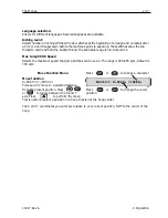
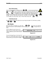
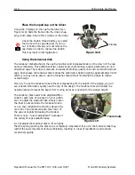
The first display (Figure2-15) shows the
design name, the current sewing speed, the
current orientation, and the current needle
number.

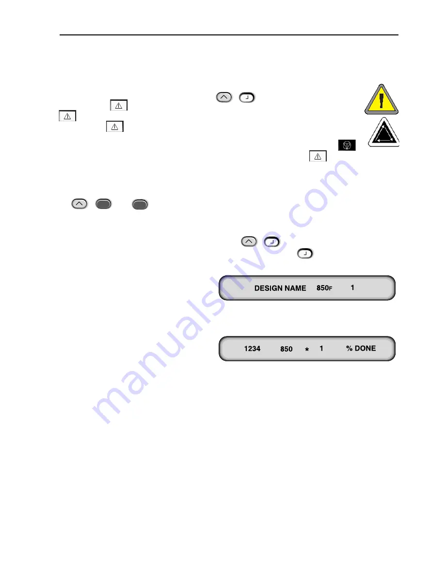
The second display (Figure 2-16) shows the
stitch count, the selected sewing speed, the
needle number, and the percent complete.

11817 Rev. A

2. Operation

Figure 2-15

Figure 2-16

Summary of Contents for EMT 10/4

Page 1: ...Installation Operation and Maintenance manual for the EMT 10T 10 4 and 10 4T embroidery peripherals Single and four head tubular embroidery peripherals Part Number 11817 Revision A ...

Page 2: ...idery Systems Melco reserves the right to revise this publication and to make changes in it at any time without obligation of Melco to notify any person or organization of such revisions or changes All precautions have been taken to avoid errors or misrepresentations of facts equipment or products However Melco does not assume any liability to any party for loss or damage caused by errors or omiss...

Page 3: ... 4 and 10 4T only 1 15 2 Operation Hazards of Operation 2 2 Threading 2 4 Tensions 2 5 Keypad 2 6 The Menus 2 8 Main Operator Menu 2 8 Disk Directory Menu 2 8 Design Menu 2 8 Color Menu 2 8 Run Design Menu 2 8 Function Menu 2 9 Options Menu 2 10 Frame Menu 2 12 Reset Menu 2 12 Service Maintenance Menu 2 12 Head Timing Menu 2 13 4 Hr Lubrication Menu 2 14 8 Hr Lubrication Menu 2 14 40 Hr Lubricatio...

Page 4: ...Menu 2 26 Run Menu 2 26 Trace the Design 2 26 Start Embroidering 2 27 Embroidery Speed 2 27 Idle Display 2 27 3 Accessories Standard Cap Frame 3 1 Wide Angle Cap Frame 3 6 Sash Frame 3 15 Spider Hoops 3 16 Lamps 3 18 Bobbin Winder 3 19 4 Operator Maintenance Installing a Needle 4 1 Cleaning 4 2 Lubrication 4 3 Time to oil hook 4 3 8 Hr Maintenance 4 4 40 Hr Lubrication Menu 4 5 80 Hr Maintenance 4...

Page 5: ...5 Troubleshooting Guide Thread Breakage 5 1 Skipped Stitches 5 2 Needle Breaks 5 2 Loose Stitches 5 3 6 Error Messages 7 Glossary of Embroidery Terms Index Quick Reference Guides Table of Contents iii ...

Page 6: ...d sewing a test design at 800 spm Recommended power conditioning equip ment LC 1800 Line stabilizer available from Accesso ry Resource Corporation Embroidering field size 28 x 50cm 11 x 19 7 with the Sash Frame 26 x 41cm 10 25 x 16 15 with a tubular frame Options Cap frame option Wide angle cap frame option Sash frame option Bobbin winder option Cart option Compatibility EDS III and Wilcom Intende...

Page 7: ...vel was measured sewing a test design at 850 spm Recommended power conditioning equip ment LC 1800 Line stabilizer available from Accesso ry Resource Corporation Embroidering field size 28 x 40 6cm 11 02 x 16 0 with the Sash Frame 26 x 41cm 10 25 x 16 15 with a tubular frame Options Cap frame option Wide angle cap frame option Sash frame option Compatibility EDS III and Wilcom Intended use The EMT...

Page 8: ...dicates a machine component will move Keep clear Shock hazard No user replaceable parts behind this label Do not open Pinch point Keep clear Pinch point Keep clear Pinch points Keep clear Needle pinch point Keep clear Use a forklift vi ...

Page 9: ...When the plastic is off refer to Figure 1 1 for further instructions Prepare the designated area for the peripheral If you have purchased the cart option you must clear a temporary location for the machine until you have assembled the cart If you purchased the foot option install the 4 feet before removing the machine from the box Two people are required to lift the EMT 10T Refer to Figure 1 2 to ...

Page 10: ...le crate is a wooden cover that protects the power switches during shipment refer to Figure 1 4 2 bolts secure this cover to the crate remove both bolts and remove the cover Along the back of the crate are 2 L shaped brackets these brackets hold the crate to the frame protecting the heads Remove the bolts holding the bracket to the crate then remove the bolts holding the bracket to the frame When ...

Page 11: ...On one end of the crate is a window of wood This end is the door Open the door by removing the nails from around the perimeter Next remove the nails from around the bottom perimeter of the box Slide the crate off the pallet Use a forklift to lift the peripheral off the pallet Place the forks in the locations shown below Figure 1 5 Do not make contact with the motors located here ...

Page 12: ...se the hand holds shown in Figure 1 6 If the machine is on a cart disengage the brakes on the indicated wheels before attempting to move the machine Engage the brakes when the machine is in the desired location Observe the precautions below You cannot remove the machine from the cart without first removing the 4 bolts securing the machine to the cart Figure 1 7 Push carefully in the directions sho...

Page 13: ... as indicated below Disengage the brakes on the indicated wheels before attempting to move the machine Engage the brakes when the machine is in the desired location Figure 1 8 Push only in the direction of the arrows when moving the machine more than a short distance Brakes ...

Page 14: ...he straight flange on piece 1 see Figure 1 10 The wheels with the brakes on them should be on the ground as shown in Figure 1 9 Insert the necessary screws M5 phillips head screw with a flat washer between the screw and the cart piece securing them tightly Attach piece 3 the same way While standing in area indicated in Figure 1 9 grasp and carefully lift cart off of cardboard and place all four wh...

Page 15: ...nding straight tighten all screws 6 Replace the side covers 7 Replace the tabletop if desired Installing the feet If you have purchased the Foot option with your EMT 10T refer to these steps to install the feet 1 Remove the main tabletop 2 Remove the side covers there are 5 screws holding each side cover in place see Figure 1 12 Use the 2 Phillips head driver included in the operator kit to remove...

Page 16: ...ns slide into place as shown in Figure 1 16 This design makes it easy to remove the tabletop to embroider tubular goods to embroider with a cap frame or to perform routine maintenance 1 Using four thumb screws for each section slide the right left and center sections into the metal channels on the table The screws are inserted from the underside of each piece 2 There is a 2 section shelf and a cov...

Page 17: ...note on the tabletops You MUST remove all 5 tabletop inserts before embroidering tubular goods or caps on the EMT 10 4 or 10 4T Failure to do so may result in damage to the equipment or bodily injury You may use parts A and B of the tabletop in Figure 1 16 in the LOW ERED POSITION to support heavy garments during tubular embroidery only Tabletop 1 9 11817 Rev A 1 Installation Figure 1 16 A B ...

Page 18: ...nnecting ANY cables 2 If your peripheral is equipped with a voltage selector switch set it to the correct position for your area 3 Plug the power cable to the rear of the unit as shown in Figure 1 18 4 Plug the other end of the cable into the line conditioner 5 Connect the line conditioner to the power source Note The fuses have been installed for the voltage in your area if you use a voltage othe...

Page 19: ...able to the leg of the unit as shown in Figure 1 19 4 Plug the other end of the cable into the line conditioner 5 Connect the line conditioner to the power source Note The fuses have been installed for the voltage in your area if you use a voltage other than the factory preset make sure you replace the factory fuses with appropriately rated fuses Refer to Chapter 4 for more information about fuses...

Page 20: ... into any port on the hub You can connect as many peripherals or computers as your hub can hold If you have more peripherals or comput ers than your hub has ports you can daisy chain 2 or more hubs together Refer to Figure 1 20 for a sample Ethernet network Note You may have as many licensed EDS III systems operating on an Ethernet network as you choose Each computer running EDS III on the network...

Page 21: ...red in memory and retrieved during each power up If the peripher al is not configured correctly it will not operate properly and may be damaged The unit name is a unique address for each machine The machine uses the unique EtherNet address as a default You may change this to any 16 or less character name Use a unique name for each machine if you have more than one machine on your network To config...

Page 22: ... dif ferent language follow these steps to select the machine language Note The machine must be configured before you can change the display language 1 Press to enter Language Selection 2 Press or to scroll through the available language selections 3 When the desired language is selected press to return to the Main Menu Note You can only change the language after the machine has downloaded the RSA...

Page 23: ... removed prior to operation Follow the steps below 1 Remove the two supports a caution tag is attached to each Refer to Figure 1 21 2 Manually move the needle case to needle 5 or 6 using or 3 Install the left and right end covers as shown in Figure 1 21 The screws for the covers are installed on the machine 11817 Rev A 1 Installation Figure 1 21 Left end cover Caution tag Support bracket Sewing he...

Page 24: ...1 16 Support brackets Operation Manual for the EMT 10T 10 4 and 10 4T Melco Embroidery Systems ...

Page 25: ...hapter outlines machine operation in addition operators must attend a Melco approved training course prior to operating the machine Figure 2 2 Thread tree Power switch Needle cases Table Figure 2 1 Power switch Table Thread tree Needle case Keypad X carriage ...

Page 26: ...on while operating the machine to prevent injury in the event of a needle break Do not wear loose or baggy clothing when operating the machine Take up Lever Oscillation Do not touch the take up levers during operation Needle Case Movements Do not place hands or other objects on or around the needle case dur ing operation Cap Frame Pinch Points Do not touch the cap frame driver or driver bar during...

Page 27: ...Do not rest hands or other objects on the table top during operation Do not reach behind the x carriage during operation with or without table top in place Rotary Hook Rotation Do not attempt to change bobbin thread during operation Do not place hands or other objects in the rotary hook area during operation Do not operate the machine without the hook guards in place ...

Page 28: ...thread through the supply tube If you do not have compressed air use the clear monofil ament approximately 24 or 70cm long provided in the operator s kit There is a small hole behind the preten sioners Push the monofilament into this hole and up through the supply tube then hook the thread on the cut and pull the thread through the tube Figure 2 3 Figure 2 4 THE THREAD PATH Numbers here represent ...

Page 29: ... just above the presser foot 11 Run the thread through the eye of the needle from front to back 12 Pass the thread through the center of the presser foot 13 Pull on the thread until you feel tensioner pressure 14 Set the tension to equal 80 120 grams required to pull the thread at the needle end 15 Fasten the thread to the retainer spring and trim the end to about an inch in length Tensions Embroi...

Page 30: ...2 7 Side Front Bobbin Bobbin case Pigtail Set screw Note the thread direction Starts embroidering sometimes referred to as the start button It is also used to exe cute selected functions in the Function menu Stops machine motion Press twice to enable manual jogs of the rack when you are in the middle of a design Used to frame forward or frame backward in idle or in the FRAME menu Holding the key w...

Page 31: ...o select values for sub menu options and for manual color changes Moves the needle position back in the embroidery field It also scrolls up a menu list It is also used to change sub menu values Moves the needle position forward in the embroidery field It also scrolls down a menu list It is also used to change sub menu values A color change enable switch hold down and use the left and right arrow k...

Page 32: ...en the Main menu and the Service Maintenance menu Disk Directory Menu Lists designs on the floppy disk in the EMT Disk Drive Use or to scroll through design names Press to load the design into machine memory Design Menu Lists designs stored in machine memory Use or to scroll through the design names Press to select a design to be sewn Up to 16 designs or up to 500K may be queued Color Menu Used to...

Page 33: ...s A power loss might occur if an error requires turning the power switch OFF and then back ON for recovery or if a power failure occurs Follow these steps to regain your position in the design and continue embroidering 1 If large garments are installed remove them from all heads while the power is OFF if you are booting from the disk drive insert the Boot Disk 2 Turn the power ON Wait for the mach...

Page 34: ... to stitch Allows you to move to a specified stitch number within a design For example you may use this function to move to a certain position in a design that may not have sewn well 1 From the Function Menu press or until the display reads Go to Stitch then press 2 Use the arrow keys to enter the desired stitch number see illustration 3 Press the machine moves to that stitch 4 If you were in the ...

Page 35: ...ine memory until changed manually or until a hard reset is performed Select hoop Lists all defined hoops The hoops will appear in the units you select during configuration i e English or Metric Remember when selecting your hoop to select the correct type and size The list of defined hoops follows 11 8 X 17 3 30 X 44cm Tube 11 8 X 14 2 30 X 36cm Tube 8 3 21cm Tube 7 1 18cm Tube 5 9 15cm Tube 4 7 12...

Page 36: ...default Disk design format Selects the format of a floppy disk when loading designs from a disk Options are DOS TAJIMA BARUDAN FMC BARUDAN FDR ZSK and NO FORMAT You must choose the format in order to load a design The NO FORMAT option will remove the Directory menu from the menu tree This saves keystrokes if you never load designs from the disk drive Select a format other than NO FORMAT to make th...

Page 37: ...ommand to insure the z axis is at its proper position Hook timing Must be done after Needle depth command to insure the z axis is in its proper position Top dead center Must be done after Needle depth command to insure the z axis is in its proper position Used to set upper dead stop position 1 degree forward Forces z axis to move forward one degree 10 degrees forward Forces z axis to move forward ...

Page 38: ...s the machine to move to the proper position for oiling Refer to the Lubrication section of Chapter 4 for the proper place to apply lubricant 80 Hr Lubrication Menu Go to this menu when the message 80hr maintenance due appears This menu forces the machine to move to the proper positions for oiling Refer to the Lubrication section of Chapter 4 for the proper place to apply lubricant 480 Hr Lubricat...

Page 39: ...etect Turns ON or OFF the Under Thread Control UTC ON is the default On the EMT 10T press or to change On the EMT 10 4 or 10 4T refer to the illustration to the right to turn it on or off on individual heads A 0 means the bobbin detect is turned on for that head a means it is turned off Bobbin detect count Allows for selection of consecutive bobbin breaks before machine stops The allowable range i...

Page 40: ... hoop limits OFF the machine will NOT beep when it encounters a rack limit during a trace You are at risk to hit the hoop when Hoop Limits are turned OFF Press or to change Design filter Filters a design when it is downloaded to the machine Filtering removes all stitches equal to or less than the selected short stitch length Jump stitches and needle ups are changed to normal stitches if their sum ...

Page 41: ... Default is 3 Max Jump Stitch Speed Selects the maximum speed that jump stitches can be sewn The range is 400 900 spm default is 700 spm Move Function Menu Move function X 00 00 in Y 00 00 in Forces an X Y move to a selected distance from the present position Press or to toggle between the X and Y axis Press to perform the move This is useful to select a position in a hoop that is not the hoop cen...

Page 42: ...he illus tration to the right Press to go on Next you must define your custom hoop s center To do this measure from the center of the needle plate to the center of the hoop in the Y direction Enter this value to define the new hoop s center Press to go on You will be prompted to save the hoop press for Yes or for No Then press to save the hoop Your custom hoop will appear in the hoop list in the O...

Page 43: ...plays the FPGA Field Programmable Gate Array rev level 5 Volt Current Displays the current supplied by the 5V power supply Sew timers Displays the total accumulated CPU time and total sew time The CPU time accumulates when the machine is turned on and the sew time accumulates when the machine is embroidering Bobbin Control Test Allows manual testing of the UTC assembly A beep will sound every time...

Page 44: ...he computer Note If you upgrade your RSA files all parameters are automatically set to their default values Configuring The EMT Disk Drive Controlled Unit If you are operating from an EDS or Wilcom network as well as using the disk drive install the correct RSA files as previously indicated and follow the rules of the network when assigning Unit names to peripheral devices Specifically after setti...

Page 45: ...wing on the display is not the design you wish to load press or until the desired design name is showing on the display then press When is pressed the disk drive light comes on as the design is loaded into the embroidery peripheral design buffer While the design is being loaded the display shows the name of the design and that it is loading When loading is complete the display will show DESIGN MEN...

Page 46: ... garment as much as possible before hooping including any lining or backing Always check the back of the garment after hooping to make sure there are no wrinkles or parts which will be inadvertently sewn Do not over tighten or over stretch the material in the hoop Be sure the inner hoop does not extend past the outer hoop on the bottom both rings of the hoop should be evenly aligned Practice To ho...

Page 47: ...ss until the display reads FUNCTION MENU then press Press or until the display reads SET HOME Press Select hoop In the Options Menu press or until the display reads SELECT HOOP Press or to scroll to the proper hoop option Press to continue Select orientation In the Options Menu Press or until the display reads Orientation Option Press or to scroll through the orientation options When the desired o...

Page 48: ... prop er holes on the X carriage for the selected hoop Use two thumb screws for each support arm see Figure 2 10 Make sure the clips on the ends where the tubular frame will attach face UP 3 Insert the hoop frames by sliding the side brackets underneath the spring clips on the support arms Make sure the slotted bracket see Figure 2 11 is to the right as you are facing the machine Slide the hoop to...

Page 49: ... front of the X carriage Remove the two thumb screws holding each support arm refer to Figure 2 10 3 Attach the flat hoop adapter bracket to the x car riage using the thumb screws Make sure the slot ted end of the adapter is facing to the right 4 Along the x carriage behind the needle case are the mounting locations for the flat hoops The mounting brackets on the peripheral are spring loaded so in...

Page 50: ... sequence Available color choices 1 10 needle number 0 pause for this color change only skip this color change P pause at this color change and all color changes thereafter A stop for applique Run Menu Press to queue the design the LCD displays the next idle menu Trace the Design Note Do NOT pull the needle or presser foot down to trace Press until the display reads FUNCTION MENU then press Press ...

Page 51: ...mplete press on the keypad To continue after a stop or thread break repair press again Embroidery Speed While the design is being embroidered you may change the speed of the machine by pressing or Idle Display While the machine is operating you may press at any time to see the Idle display There are two screens available in the Idle display press to toggle between them The first display Figure2 15...

Page 52: ...2 28 Quick Start Operation Manual for the EMT 10T 10 4 and 10 4T Melco Embroidery Systems ...

Page 53: ... access to the cap frame mounting brackets under the head Special note for the EMT 10 4 and 10 4T You MUST remove all 5 tabletop inserts before embroidering caps on the EMT 10 4 or 10 4T Fail ure to do so may result in dam age to the equipment or bodily injury Refer to Chapter 1 for more information Also correlate the number on the driver with the number on the head to ensure sew quality 2 Select ...

Page 54: ...ss to go to the Function menu then press select Go to Hoop Cen ter and press to center the hoop First time adjustment The first time you install the standard cap frame driver s you must adjust them to your peripheral to ensure sew quality Follow these steps to adjust the driver s 1 Install the drive s onto the head s if you have not 2 Loosen the four button head screws across the top of the drive ...

Page 55: ...e of the cap 4 If you are using backing place it inside the cap 5 Slide the cap on the hoop frame so that The brim of the cap is away from you The front of the cap is up The sweat band is under the square retainer at the center of the frame The sides of the cap are inside the outer arms of the cap frame 6 Push the cap onto the cap frame until the embroidery field is centered Since caps come in dif...

Page 56: ...g a raised needle plate use spacers to raise the presser foot 1 Remove the two screws attaching the standard needle plate and replace the standard plate with the raised plate Use the same screws to attach the raised needle plate The needle should be centered in the hole in the raised needle plate 2 Remove the lower cover on the front of the needle case It is not necessary to remove any thread 3 Us...

Page 57: ...s to NEEDLE DEPTH The presser foot should be 0 040 from the needle plate 11 Verify the presser foot is clearing the needle plate by 0 030 to 0 050 If needed add or remove the necessary combination of the 0 020 or 0 040 spacers to achieve the appropriate clearance Go to step 9 to rotate the machine to HEADUP to add or remove spacers Note If you add too many spacers you may overcompress the presser ...

Page 58: ...letop sections 2 Make sure that the cap supports are extended if they are not extend them refer to the Technical manual for more information 3 Make sure that the 3 socket head cap screws along the interface bracket Figure 3 7 and 4 socket head cap screws which hold the bearing housing Figure 3 8 are slightly loose 4 Move the beam all the way back towards the rear of the peripheral using the periph...

Page 59: ...le side to side movement 9 Push on the driver bar to move the driver from front to back several times making sure the dri ver moves freely Tighten all 4 screws on the bearing housing Special note for the EMT 10 4 and 10 4T Apply the number sticker that is provided to the driver bar and to the head if it wasn t marked at the factory The drivers should always be installed on the same head of the sam...

Page 60: ...e restriction If the driver bar does not firmly contact the drive ring loosen the 3 socket head cap screws and repeat step 14 14 Carefully and firmly tighten all 3 socket head cap screws along the interface bracket without allowing the bracket to move 15 Repeat steps 11 through 14 for the remaining drivers if necessary 16 Press to go to the Function menu then press select Go to Hoop Center and pre...

Page 61: ...e head to ensure sew quality 2 The Wide angle cap frame hoop size will be automatically selected 3 Press to go to the Function menu then press select Go to Hoop Center and press to center the hoop 4 Under the cylinder arm locate the cap frame mounting brack ets see Figure 3 13 The female dove tail mount ing bracket under the needle area The rear mounting bracket with a round hole at the rear of th...

Page 62: ... on the mounting brackets first and then attach the driver to the beam This will improve the quality of your embroidery The tensioner disk To install the tensioner disk follow these steps 1 Loosen the two thumb nuts on the back of the wide angle cap frame driver see Figure 3 15 2 Insert the tensioner guides into the two holes in the front of the wide angle cap frame driver through the two thumb nu...

Page 63: ...e has a metal strap with a buckle at its end Make sure this buckle is attached by screws in its OUTSIDE two holes NOT the inside two holes 2 Now slide the cap frame onto the gauge making sure the locating ele ment on the cap gauge fits into the cap frame s notch and the cap frame slips firmly under the two roller clips 3 For the best sew quality use the rub ber strip it provides appropriate spac i...

Page 64: ...nly about 1 4 of braid from where it s sewn to the cap 10 Now place the cap on the cap frame The sweatband should be under the locator and the brim should be cen tered and pointing up 11 Pull the side of the sweatband toward the cap frame and down 12 Flatten any bunching of the sweat band by folding it over and toward the hoop 13 To secure the sweatband swing the metal strap up and over the sweat ...

Page 65: ...etighten the wing nuts 17 Pull the elastic brim holders over the cap s brim to the front Pull the wrin kles out of the cap using light ten sion To secure the cap fabric attach two clips 18 to each post The clips are applied with the handles angled down and toward the center of the cap 19 You may now remove the cap hoop from the gauge Remember to also remove the rubber strip Your cap is now properl...

Page 66: ... 23in 6mm you may not be able to use the tensioner disk without modifying the design to reduce overall height If you try to use the tensioner disk without compensating for the height of the design you will see reduced embroidery quality near the top of the design The tensioner disk will contact the needle plate and prevent the beam from moving as far as is needed for the design height The tensione...

Page 67: ...erent crown sizes Remember if you are planning to use the tensioner it reduces the embroidery field s height by approximately 0 23in 6mm Wide Angle Cap Frame 3 15 11817 Rev A 3 Accessories Y A 1 18 X 14 25 Where Y height of the sewing field in inches A height of the crown in inches Y A 30 X 362mm Where Y height of the sewing field in millimeters A height of the crown in millimeters Tip ...

Page 68: ...en its shading then move on This helps to elim inate the push pull tendency of the fabric of the cap Underlays should follow this rule too If you have a lot of running stitches in a design consider converting them to satin stitches Running stitches have a tendency to lose registration With large designs try to alternate the direction of the stitches This helps to eliminate the push pull tendency o...

Page 69: ...fabric adhesive This procedure reduces hooping time and permits a high rate of production on parts of preassembled garments like labels patches collars and pockets Installing the Sash Frame Follow these instructions and see Figure 3 20 1 Before installing the sash frame make sure the table tops are in place Without the sup port of the table tops the sash frame may be damaged 2 Guide the sash frame...

Page 70: ...a corner The thumb rail should be facing away from the embroidery field 3 Attach 6 of the 300cm clips along the back of the frame on the EMT 10 4 or 10 4T use 1 220cm clip and 1 300cm clip along the back of the frame on the EMT 10T 4 Pull the fabric taut and attach the same number of clips at the front of the frame 5 Attach one 220cm clip to each end of the frame on the EMT 10 4 or 10 4T and one 2...

Page 71: ... Figure 3 21 Secure the spi der with the 21cm hoop tightener 4 Referring to Figure 3 21 slide bracket A into place on the thumb screw at the rear of the sash frame then swing bracket B into place on the thumb screw at the front of the sash frame 5 Tighten the thumb screws 6 Repeat for all embroidery heads on the EMT 10 4 or 10 4T Note After using the spider hoops and BEFORE embroidering with the f...

Page 72: ...t bulb from Melco one is provided in the operator kit EMT 10 4 or 10 4T The EMT 10 4 has built in fluorescent lights above the table The lights have a separate ON OFF switch located next to the main power switch see Figure 3 23 Push to turn the lamp ON or OFF To change the bulb turn the power off twist the old bulb slightly then remove Align the contacts on the new bulb with the contacts on the ma...

Page 73: ...stitch quality of finished embroidery Bobbin tension requires adjustment for good embroidery with any thread The weight of the thread selected and the tension used when wind ing will also determine the amount of thread on the bobbin and therefore the frequency of bob bin changes For most applications a cotton thread or a core spun cotton composition thread such as RASANT in a 40 or 50 weight DTEX ...

Page 74: ...e position of the Bobbin Full switch on the actuator lever using the two screws on top of the lever The level of fill should be set to approximately 80 of the bobbin capaci ty or about 0 04 1mm below the edge of the spool flange 4 Move the actuator lever to the OFF position remove the wound bobbin and break or trim the thread tail A properly wound bobbin is shown in Figure 3 28 item A Items B thro...

Page 75: ...e with the aluminum bobbin spool p n 008499 01 provided with the unit If bobbin spools from other sources are used the bobbin may be improperly retained on the bobbin winder shaft Most non standard bobbin spools have a slot in the spool hub that engages the bobbin winder shaft spring and holds the bobbin in place If this type of bob bin spool is used you must reposition the shaft spring Refer to F...

Page 76: ...nance When the bobbin winder is subjected to heavy or continuous operation you may need to lubricate the bobbin winder shaft Apply one drop of sewing machine oil to the bobbin winder shaft as shown in Figure 3 31 Rotate the bobbin winder shaft by hand until the shaft moves smoothly and freely Figure 3 31 Oil here ...

Page 77: ...he scarf of the new needle toward the rear of the head slide the needle into the needle bar as far as it will go and re tighten the set screw The eye of the needle should be facing directly forward Thread Break Switch Each head has a thread break switch below the tensioners with ON AUTO and OFF positions see Figure 4 2 The switch controls whether the individual head stitches as it moves through a ...

Page 78: ... a mild detergent and water Wring out the cloth before wiping the surfaces Do not get water or any other fluids inside the machine or on any of the working mechanical surfaces Note If an accidental spill occurs wipe it up immediately with a clean dry cloth and allow the machine to dry completely before turning the power on The Rotary Hook Area 1 Clean this area once per month with the machine powe...

Page 79: ...ress the machine will move to its next position Refer to these pages to oil each component throughout the process When you have completely stepped through each menu the display will be cleared The message will display at the end of each design You can press any key to temporarily clear the message but you must perform the required maintenance to clear the message until the mainte nance is required...

Page 80: ...4 4 to lubricate the cap frame driver shaft Press when done The y rail will move back and forth to distribute the oil If you are using a Wide Angle Cap Frame go into the 8 hour lubrication menu then press Press or until wide angle driver shaft guide appears then press the x carriage will move to the front Wipe the lint off both driver shafts see Figure 4 5 Place one drop of oil on the Driver shaft...

Page 81: ...e head Press when done You must perform this operation to clear the message 80hr maintenance due When this message appears go into the 80 hour lubrication menu then press Refer to the steps below to lubricate each area Note If you have a cap frame driver attached you must remove it before stepping through this menu 1 When upper lower needle bar displays press No motion is required Refer to Figure ...

Page 82: ...ossible To access these areas on the EMT 10 4 or 10 4T insert the oiler through the hole with the red bushing on the front of the panel Use a flashlight if needed Press to move the needle case to needle 10 Oil the needle bar driver as shown in Figure 4 10 Also lubricate the v rail on this side of the head Press when done The head will move back and forth to distribute the oil Figure 4 9 Top view o...

Page 83: ... rail Press when done the y rail will move back and forth to distribute the oil The y rails on the EMT 10T are not located directly under the slot you must angle the oiler slightly toward the mid dle of the machine to reach the rails Figure 4 13 shows the location of the rails with the side panel removed 11817 Rev A 4 Operator Maintenance Lubrication 4 7 Figure 4 12 Place 1 2 drops on both the fro...

Page 84: ...hen trimmer knife drive arm front pin displays press No motion is required to lubricate the trimmer knife drive arm and pin Remove the needle plate Refer to Figure 4 16 to lubricate the trimmer knife drive arm and pin Press when done Replace the needle plate Figure 4 15 Put 1 drop of oil at all four loca tions moveable frame Top view with cover removed Figure 4 16 Put 1 drop of oil on each locatio...

Page 85: ...aluminum cover there are 6 screws along the top of the cover Remove all 6 screws then carefully lift the cover off the x carriage The x carriage is a metal beam with a groove along the front and back along the top edge When you oil the x carriage make sure you put one drop of oil in the groove on each side of the metal beam Figure 4 18 shows the groove along the front of the x carriage there is an...

Page 86: ...stribute the grease 2 When take up lever cam and follower displays press This causes the needle case to move to needle 1 for proper lubrication Use a cotton swab and a SMALL AMOUNT OF GREASE to lubricate the take up lever cam and follower Refer to Figure 4 22 to lubricate the take up lever cam and follower Use a flashlight if necessary For an EMT 10 4 or 10 4T you must remove the end cover to acce...

Page 87: ... rear support bracket Pull the driver shaft and driver shaft guide out the front of the driver until the bearings are exposed see Figure 4 27 Place 10 drops of oil on the bearings Push the driver shaft and driver shaft guide up through the bearing housing Attach the rear support bracket and tighten the 2 screws Press when done You must perform all operations to clear the message 11817 Rev A 4 Oper...

Page 88: ...pull on the cover to remove the fuse holder see Figure 4 29 4 Change the fuses then replace the fuse holder 5 Reconnect the power cord and turn on the power Tool Kit The tool kit contains the following items and is included in the operator s kit 4 12 Replacement Parts PERIPHERAL 115V RATING Melco part number 230V RATING Melco part number EMT 10T 5 A 010162 05 5 A 010162 05 EMT 10 4 10 A 010162 10 ...

Page 89: ...861689 01 LUBRICANT GREASE T517 2 OZ 001532 01 BAR NDL 006846 01 KIT TOOL UNIVERSAL 007505 01 SHIM NDL CS 110113 01 WARRANTY STATEMENT LIMITED 12 M 003772 03 NEEDLE ARC 80 12FG 10 PK 16 X 005577 01 BUMPER WASHER 001528 01 CLAMP NDL ASSY 001537 01 SPRING HLDING NDL BAR 007559 01 SPRING CHECK TNSNR THD 007591 01 DAMPER NDL CLAMP 009027 01 GAGE COMBINATION UTC 005917 01 DISK RSA FILES 2 DISKETTES ED ...

Page 90: ...your Melco Representative to verify which kit is right or your machine PART NUMBER DESCRIPTION 010369 01 CABLE ETHERNET NTWRK INTFC 10871 PCB KYBD W KEYCAPS DISPLAY EMT ASSY 10711 PCB CPU ASSY 009419 01 PCB MOTOR DRIVER EMT10 ASSY 009000 01 HOOK ROTARY SM BOBBIN 004267 01 CASE BOBBIN 007924 01 FOOT PRESSER ASSY 005617 01 KNIFE MOVABLE 009411 01 PCB CLR CHNG EMT ASSY 010107 01 UTC ASSY 344924 01 ST...

Page 91: ...nical items for the EMT 10 4T 11817 Rev A 4 Operator Maintenance p n 010901 01 PART NUMBER DESCRIPTION 010689 01 CABLE ETHERNET NTWRK INTFC 50 010107 01 UTC ASSY 001532 01 BAR NDL 007924 01 FOOT PRESSER ASSY 008490 01 CASE BOBBIN SM W SPRING 009000 01 HOOK ROTARY SM BOBBIN 006520 01 PLATE NEEDLE UTC 001840 01 CLAMP STOP NDL BAR 003586 01 BLADE GRABBER 008471 01 VELCRO GRABBER FLARRED 001528 01 CLA...

Page 92: ...0107 01 UTC ASSY 009407 04 PCB INTFC ASSY EMT 10 009411 01 PCB CLR CHNG EMT ASSY 001532 01 BAR NDL 007924 01 FOOT PRESSER ASSY 008490 01 CASE BOBBIN SM W SPRING 009000 01 HOOK ROTARY SM BOBBIN 006520 01 PLATE NEEDLE UTC 001840 01 CLAMP STOP NDL BAR 001528 01 CLAMP NDL ASSY 001828 01 SCREW SET NDL CLAMP 010027 01 PCB ESTOP ASSY EMT 10 4 10871 PCB KYBD W KEYCAPS DISPLAY EMT ASSY 007505 01 SHIM NDL C...

Page 93: ...ASSY 001532 01 BAR NDL 007924 01 FOOT PRESSER ASSY 008490 01 CASE BOBBIN SM W SPRING 009000 01 HOOK ROTARY SM BOBBIN 006520 01 PLATE NEEDLE UTC 001840 01 CLAMP STOP NDL BAR 001528 01 CLAMP NDL ASSY 001828 01 SCREW SET NDL CLAMP 007505 01 SHIM NDL CS 110231 01 LILST HARDWARE SPARE 4 HD 004803 01 ASSY PKNG SPARE PARTS KIT 010902 01 KIT FUSE EMT 10 4 T ...

Page 94: ...09411 01 PCB CLR CHNG EMT ASSY 001532 01 BAR NDL 007924 01 FOOT PRESSER ASSY 008490 01 CASE BOBBIN SM W SPRING 009000 01 HOOK ROTARY SM BOBBIN 006520 01 PLATE NEEDLE UTC 001840 01 CLAMP STOP NDL BAR 003586 01 BLADE GRABBER 007545 01 VELCRO WIPER PILE 001528 01 CLAMP NDL ASSY 001828 01 SCREW SET NDL CLAMP 005600 01 KNIFE SPRING FIXED 006671 01 PRESSER UNDER THREAD 005617 01 KNIFE MOVABLE 10871 PCB ...

Page 95: ...orrectly refer to threading section Upper bobbin tension Upper bobbin tension too tight Loosen upper bobbin tension Ratio of upper thread to bobbin thread incorrect Adjust upper and or bobbin tension see tension section Incorrect check spring tension stroke Adjust replace check spring refer to the technical manual Fabric and hoops Fabric is hooped loosely Tighten fabric in the hoop see hooping sec...

Page 96: ...r broken presser foot prevents the needle from coming out of the fabric smoothly Replace or strengthen the spring refer to the technical manual Thread Thread twist is too tight Use the appropriate thread or consult the service department for suggestions Thread is too elastic to form an adequate loop Check spring The check spring stroke is too high Adjust the check spring stroke refer to the techni...

Page 97: ...ok timing is incorrect Adjust hook timing refer to the technical manual Inadequate rotary hook lubrication Lubricate the rotary hook see the rotary hook lubrication section Design density too tight Decrease density refer to the EDS manual for design editing Gap between UTC retaining tab and hook too wide Adjust gap see the UTC adjustments section ISSUE SOLUTIONS Bird Nesting Thread may be wrapped ...

Page 98: ... that the driver was properly adjusted on the peripheral Puckering Modify the design Check that the tensioner is not installed too tightly Loss of registration Adjust cap supports Modify the design Check that the tensioner is not installed too tightly Check the driver bar cable tension Check the spindle adjustment Check that the driver was properly adjusted on the peripheral Cap frame is loose on ...

Page 99: ...ted here or if you do not know how to respond to a message that is listed here contact your Melco service representative for assistance Application Run Means that the peripheral did not download properly The machine must be turned OFF then turned ON again If this does not work try reconfiguring your peripheral If this still does not work try reinstalling the software Call your Melco service repres...

Page 100: ...proximate stitch or color change number you can use the Goto Stitch or Goto Color function 2 Press If that doesn t work turn the power OFF and then back ON make sure the computer is on and you are in EDS III or Wilcom software Check Bobbin See Thread Break Color Change Axis Current Limit This message means that the drive circuit of the Color Change axis motor has detected excess power This is caus...

Page 101: ... Design from the Reset menu then delete the design Design Job Buffer Full Means that no more information may be stored in the peripheral s job queue This will be dis played in the Run Menu Design Not Found This message displays during a Power Fail Recovery if the machine cannot find the last design that was sewing in the design buffer Resend the last design from the disk drive and try the Power Fa...

Page 102: ...is motor has detected excess power This is caused by a jammed Grabber axis motor or a malfunction of the motor or electronics Turn the machine OFF then back ON to recover If this error occurs more than once during a design call your representative for assistance Grabber Not Home Means the thread grabber is not fully retracted to its home position The grabber may be caught perhaps on the thread or ...

Page 103: ...ative for help Motor Command Buffer Full The motor command buffer is full You may have created more Move commands or Head Timing commands than the buffer can hold To clear the MC buffer turn the power OFF then back ON If cycling the power does not clear the screen message there may be an error in the CPU Reconfig ure your peripheral If this still does not clear the message call your Melco service ...

Page 104: ... the needle case On the EMT 10 4 and 10 4T it is on the right side of head 1 as you are facing the machine behind the needle case Figure 6 1 shows the locations on an EMT 10T The LED and screw are in the same locations behind head 1 on an EMT 10 4 or 10 4T 2 There is an LED on the top of the arm that supports the head When this light is ON the head is OFF INDEX Turn the screw until the light goes ...

Page 105: ...Maintenance Menu and Enable the trim function then pro ceed Trimmer Not Home This message is displayed when is pressed to begin sewing or a Head Timing Func tion is performed but finds the cutting blade is not in its home position Move the trimmer to the home position manually then continue sewing If this does not fix the problem call your Melco representative X Axis Current Limit This message mea...

Page 106: ...ctually sewing Y Axis Not Done This means the needle is trying to enter the cloth before the X or Y motion is complete Try to continue sewing if error returns call your Melco service representative Y Axis Tracking Error This error message means the Y axis motor is not tracking or moving as commanded by the Y axis controller software This error can occur during sewing trims tracing framing and duri...

Page 107: ...read or insufficient lubrication Locate and correct the problem If you cannot locate the problem or if this message continues to occur often call your Melco service representa tive Z Axis Tracking Error This means the Z axis motor is not tracking as commanded by the Z axis controller software Exe cute the Go to Headup option in the Function Menu Exit the Function Menu and press the key to continue...

Page 108: ...6 10 Error Messages Operation Manual for the EMT 10T 10 4 and 10 4T Melco Embroidery Systems ...

Page 109: ...om the sewing peripheral after the design has sewn once Machine will display Bad Design Name when the design finishes AUTO RUN An option that automatically sends a design to the beginning of the job queue allowing you to sew without making any selections from the peripheral menus AUTO TRIM An option that automatically inserts a trim command between each letter of any alphabet includ ing scripts us...

Page 110: ...s BIT PAD Another name for a Digitizing Tablet BLOCK A designated group of stitches that can be scaled rotated repositioned deleted cut copied and pasted BLOCK EDIT The term used for changing a defined group of stitches BOBBIN The reel or spool that holds the under thread of machine sewing The under thread itself C CENTER DESIGN Positing the design in the center of the sewing field CHAIN STITCH A ...

Page 111: ... making the complete fill of an irregular shape CONDENSED FORMAT A coding format that includes only the data for the Mk entries and function commands created during digitizing This format allows you to scale the design up or down as well as change the density and stitch length of the design COPY A command that keeps the design in the current window and also stores it in a temporary memo ry called ...

Page 112: ...ed group of computer files stored on one of your computer drives The hard drive of your computer is usually the C directory Floppy diskettes are inserted into the A or B drive The CD ROM drive is usually the D drive DISK A computer data storage device which is accessed in the hard drive or one of the floppy drives The hard drive of your computer is usually the C drive Floppy diskettes are the A or...

Page 113: ...ify the type of file F FILE A collection of information named and stored on a disk Every piece of information on your com puter s hard drive is stored in a file FILE NAME The unique identifier given to a design that is stored on a computer The file name can have up to eight characters a period and an up to three letters extension FILL STITCH A series of running stitches used to cover large areas F...

Page 114: ...ly the C drive HOOP A device made of wood metal or plastic used to hold a garment or fabric taut during the embroidery process HORIZONTAL SPACING Additional spacing that may be added between Alphabet letters I ICON A small graphic representation of something larger IMPORT Bringing a design file into the EDS III program from a non DOS formatted diskette or paper tape INSERT Adding additional inform...

Page 115: ...e needle position prior to sewing The sewing will stop at the bottom right and will not return to the original position It will sew above Y 0 and to the right of X 0 used to position design used to align to the right of a vertical line such as a plaquet LINE SPACING Adding space between lines of lettering in the same text box Line space is determined by adding the letter height to the amount of bl...

Page 116: ...ery machine with more than one sewing head N NEEDLE UP A command used to move from one part of a design to another without stitching NON DOS FORMATS Any disk format other than DOS that is supported by EDS III such as Melco Tajima Barudan ZSK NORMAL STITCH A command that resets the stitching to a regular running stitch It also brings the needle down to the sewing position after a needle up function...

Page 117: ...this sequence changes the texture of a fill PERIPHERAL Any device that is attached to or run by the computer Embroidery Machines Paper Tape Punches Digitizing Tablets Printers or Plotters PERIPHERAL SETUP A dialog box that allows you to select Embroidery Peripherals in your network PERIPHERAL STATUS A dialog box that displays information about a particular peripheral POINT EDIT WINDOW One of the w...

Page 118: ...SCALING The process of changing the size density or stitch lengths in a design SCROLL BAR A bar that appears at the far right or bottom edge of a window or list box whose contents are not fully visible Clicking on the arrows of the bar moves the viewing portion of the screen SEND DESIGN Sends all items on the screen together under one design name The design can be a condensed expanded or object fi...

Page 119: ...SOR An EDS III option that changes the size densities or stitch lengths of an expanded design STORED SYMBOL A portion of a design that is digitized as a separate piece to be used multiple times within the same design An example of this would be a leaves on a tree You would digitize one leaf as a stored symbol then use that same leaf and place it on the tree at various different sizes and angles Th...

Page 120: ...BOBBIN The UTC also has a retaining tab that holds the inner basket of the rotary hook The UTC am must be set close enough to allow the thread to move it as stitches are made Incorrect alignment of the UTC generates repeated Check Bobbin error messages V VERTICAL SPACING A command that stair steps your lettering up positive value or down negative value W WINDOW A rectangular area on your screen in...

Page 121: ...4 4 A Accessories 3 1 Accumulate needle ups 2 15 Application Run 6 1 B Bad Design Name 6 1 Bad Head Timing Function 6 1 Bad Instruction 6 1 Bad Keyboard Code 6 2 Bad Power Fail Recovery Pointer 6 2 BIOS rev level 2 19 Bobbin Control Test 2 19 Bobbin detect count 2 15 Bobbin detect 2 15 Bobbin Winder 3 21 Bottom tensions 2 6 C Cap designs 3 16 Cart Assembly 1 6 Center design 2 12 Center hoop 2 23 C...

Page 122: ...sk Load Error 6 3 DSP Command Error 6 4 Duplicate Design 6 4 E Embroider 2 27 Embroidery Speed 2 27 EMT 10 4 and 10 4T Specifications v EMT 10T Specifications iv Error Messages 6 1 E stop Engaged 6 4 Ethernet network 1 12 F First powerup 1 13 Flat hoops 2 25 Format 2 21 Format Selection 2 21 Found End of Design 6 4 FPGA rev level 2 19 Frame Menu 2 12 Function Menu 2 9 Function Not Allowed 6 4 Fuse...

Page 123: ...8 K Keypad 2 1 2 6 L Lamps 3 20 Language selection 1 14 Language selection 2 17 Loading a Design 2 21 Loading Design Try Again 6 5 Lock stitch 2 15 Lubrication 4 3 M Machine Running 6 5 Main Operator Menu 2 8 Main tensioners 2 6 Maintenance 4 1 Max Jump Stitch Speed 2 17 Menu 2 8 Missed Headup 6 5 Motion Controller rev level 2 19 Motor Command Buffer Full 6 5 Move function 2 17 Move Function Menu ...

Page 124: ... 12 Return to design origin at EOD end of design 2 15 Return to last stitching position 2 10 Return to origin 2 10 RSA Files 2 20 RSA rev level 2 19 Run Design Menu 2 8 Run Job Error 6 7 Run Menu 2 26 S Sash Frame 3 17 Select a design 2 26 Select hoop 2 11 2 23 Select orientation 2 23 Service Maintenance Menu 2 12 Set home 2 23 Set home 2 9 Sew timers 2 19 Spare Parts 4 14 Spider Hoops 3 18 Standa...

Page 125: ...Trimmer Not Home 6 7 Trimmer tail length 2 15 Troubleshooting 5 1 Tubular hoops 2 24 Turbo mode 2 12 U Unit of measure 2 16 Unpacking 1 1 W Wide angle cap frame 3 6 X X Axis Current Limit 6 7 X Axis Move Timeout 6 7 X Axis Not Done 6 7 X Axis Tracking Error 6 7 X Y Home is not Set 6 8 X carriage 2 1 Y Y Axis Current Limit 6 8 Y Axis Move Timeout 6 8 Y Axis Not Done 6 8 Y Axis Tracking Error 6 8 Z ...

Page 126: ...INDEX Operation Manual for the EMT 10T 10 4 and 10 4T ...

Page 127: ...Quick Ref erence Guide for the EMT 10T 10 4 and 10 4T 11817 Revision A ...

Page 128: ...machine name READY then shows the design name 7 Press until the display reads FUNC TION MENU 8 Press 9 Press or until the display reads TRACE DESIGN OUTLINE 10 Press First the display reads CALCU LATING then shows the design name 11 Press The trace function begins Repeat by pressing again 12 When ready to sew press then press 13 Press to begin embroidering Select a Hoop Size 1 Press until the disp...

Page 129: ...m 8 3 21 cm 7 1 18 cm 5 9 15 cm 4 7 12 cm Round Wooden Frames 8 3 21 cm Spider Frames 7 1 18 cm 5 9 15 cm 4 7 12 cm 3 5 9 cm 2 8 7 cm Cap Frames 2 8 x 5 6 7 cm x 14 2 cm Large Cap Frame 2 5 x 5 6 6 3 cm x 14 2 cm Small Cap Frame 2 8 x 14 3 7 cm x 36 2 cm Wide Angle Cap Frame Other Frames Sock Hoop Sash Frame Frame Sizes ...

Page 130: ...EMT MENU AND COMMAND QUICK REFERENCE ...

Reviews: