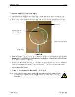
Wide-Angle Cap Frame
3-7
11817 Rev. A
3. Accessories
Note: When pushing the driver shaft into the hole in
the rear mounting bracket, make sure the cap
supports are positioned over the needle plate.
This prevents the shaft from binding.
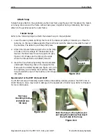
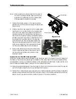
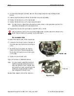
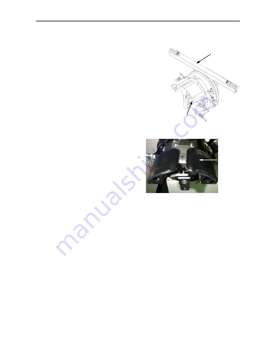
7. Tighten the thumb screws on the rear mounting
bracket and on driver dove-tail support bracket (see
Figure 3-10).
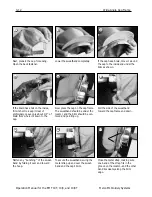
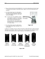
8. Position the driver cap supports on the needle plate
(see Figure 3-11), center them to the needle plate
hole and in the same time adjust their position in
up-down direction by moving driver up-down on
the slots in the bearing housing and slightly tighten
at least one socket cap screw on the bearing hous-
ing using 4mm hex allen wrench. The cap sup-
ports should touch the needle plate lightly and
the driver should slide freely from front to back
without any restriction; the cap supports should
not have any visible side to side movement.
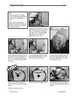
9. Push on the driver bar to move the driver from
front to back several times, making sure the dri-
ver moves freely. Tighten all 4 screws on the
bearing housing.
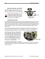
Special note for the EMT 10/4 and 10/4T
Apply the number sticker that is provided to the driver bar and to the head if it wasn’t marked at
the factory. The drivers should always be installed on the same head of the same peripheral they
are adjusted on; when you install the drivers on the peripheral at a later date, make sure the num-
bers correspond. Repeat steps 2 through 9 for the remaining drivers.
10. Using the peripheral keypad, move the beam to the front of machine and connect the cap dri-
ver to the beam using the two hoop interface thumb screws.
11. Tighten the 3 socket-head cap screws along the interface bracket until they barely contact the
bracket using provided 3mm short arm hex allen wrench. The interface bracket should still be
able to move in up-down direction. Refer to Figure 3-7 for screw locations.
Figure 3-10
Thumb screw
Figure 3-11
Cap
Support
Driver bar
Summary of Contents for EMT 10/4
Page 52: ...2 28 Quick Start Operation Manual for the EMT 10T 10 4 and 10 4T Melco Embroidery Systems ...
Page 108: ...6 10 Error Messages Operation Manual for the EMT 10T 10 4 and 10 4T Melco Embroidery Systems ...
Page 126: ...INDEX Operation Manual for the EMT 10T 10 4 and 10 4T ...
Page 127: ...Quick Ref erence Guide for the EMT 10T 10 4 and 10 4T 11817 Revision A ...

