3-8
Wide-Angle Cap Frame
Operation Manual for the EMT 10T, 10/4, and 10/4T
Melco Embroidery Systems
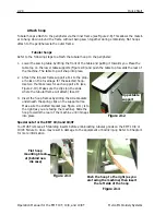
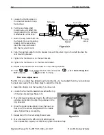
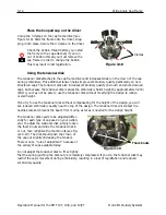
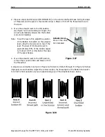
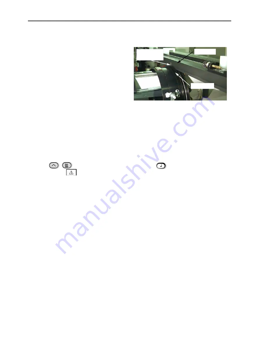
12. Level the interface bracket. To do this, first
move the beam all the way to the left, by
pushing on the X-carriage. Make sure that
there is no gap between the driver bar and
driver ring (see Figure 3-12). If needed, press
down lightly on the bar and tighten the cor-
responding socket-head cap screw on the
interface bracket slightly. Then, by pushing on
the X-carriage, move the beam all the way to
the right and repeat the procedure.
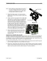
13. Repeat moving the driver all the way to right and left, watching closely to ensure that the dri-
ver bar firmly contacts the driver ring and moves with no visible restriction. If the driver bar
does not firmly contact the drive ring, loosen the 3 socket-head cap screws and repeat step
14.
14. Carefully and firmly tighten all 3 socket-head cap screws along the interface bracket without
allowing the bracket to move.
15. Repeat steps 11 through 14 for the remaining drivers if necessary.
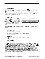
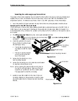
16. Press
to go to the Function menu then press
; select
Go to Hoop Center?
and press
to center the hoop.
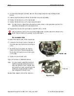
Your wide-angle cap frame driver(s) are fully adjusted and ready for use.
IMPORTANT
If you wish to use the adjusted cap frame option on a different peripheral, check the adjustment
on the new peripheral to ensure proper sew quality.
This adjustment only needs to be performed the first time the cap frame driver is installed on a
machine.
The Wide-angle cap frame does NOT require the use of raised needle plates.
Figure 3-12
Driver bar
Driver ring
Check for
contact here
▲
Summary of Contents for EMT 10/4
Page 52: ...2 28 Quick Start Operation Manual for the EMT 10T 10 4 and 10 4T Melco Embroidery Systems ...
Page 108: ...6 10 Error Messages Operation Manual for the EMT 10T 10 4 and 10 4T Melco Embroidery Systems ...
Page 126: ...INDEX Operation Manual for the EMT 10T 10 4 and 10 4T ...
Page 127: ...Quick Ref erence Guide for the EMT 10T 10 4 and 10 4T 11817 Revision A ...


