12616, Rev. B
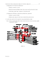
12. Adjustment of Bobbin Thread Sensor, Solenoid and Thread Breakage Sensor.
31
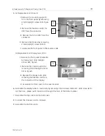
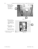
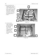
V.Turn on power switch.
Turn volume VR2(C) until
the green LED starts
blinking goes on and off.
(dust sensor adjustment).
VI.Set thread wound
bobbin (9m) in a bobbin
case. Embroider a
suitable design, which is
transferred from EDS3.
Upper thread is not used
in this case. Hold the
upper thread tension
spring at the "on"
position by clip. (If you do not have a controller, turn on adjustment test equipment then
drive a motor.) Turn volume VR1(D) until the red LED starts blinking (bobbin thread
sensor adjustment). Be sure adjusting volume VR1 after adjusting VR2.
VII.Set thread wound bobbin (15m) in a bobbin case, then embroider again. Confirm that
the message "BOBBIN THREAD" does not appear.
2. Adjustment of the Solenoid.
•
Adjust the solenoid with the operation stroke set to be less than 2mm. If the solenoid is replaced,
the thread tension release function must be adjusted.
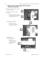
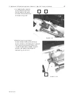
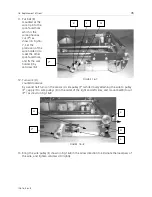
I. Set the stitch balancing thread
tension dial (E) to[9]. Make sure
that the thread tension release is
secure under the stop condition
of the machine. If the stitch
balancing thread tension dial is
functioning, loosen setscrew(F),
and fix setscrew(F) by relocating
the thread tension release plate
(G) leftward.
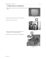
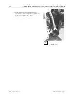
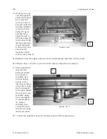
II.Set stitch balancing thread
tension dial (E) to [0] as shown in
Fig.12-4. Operate the machine,
and make sure that the solenoid
functions to produce a gap
between the thread tension
release plate (1)(G) and the disk presser, and the stitch balancing thread tension is
applied. If the stitch balancing thread tension is not applied, loosen setscrew (F), relocate
thread tension release plate (1)(G) rightward, and fix setscrew (F).
III. Make sure that condition (I) and (II) are satisfied.
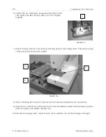
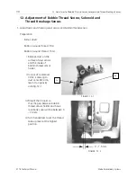
FIGURE 12-3
C
D
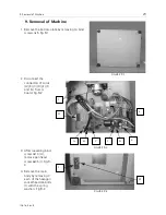
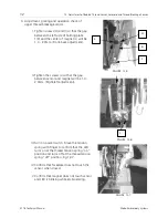
FIGURE 12-4
F
G
E

