background image

12616, Rev. B

13. Replacement of Wire pulley

33

13. Replacement of Wire pulley

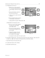
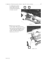
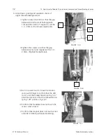
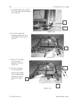
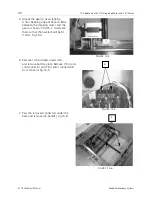
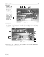
 1. Remove the X-Y cover and 

then, remove the X-Y 
mechanism from the 
baseplate.

 2. Draw the bushing (A) out of 

the X-Y mechanism, and 
draw out cushion (B) 
sideways.

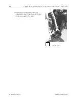
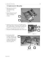
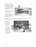
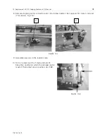
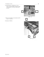
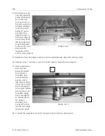
 3. The gear (C) shown in Fig. 13-3 is protruded from the 

bottom face of the X-Y mechanism. Insert a bolt by nut 
(D), so that the gear (C) is free of being scratched when 
erecting the X-Y mechanism as shown in Fig. 13-3.

Work (1)-(3) are applicable when removing the X-Y 
mechanism from the baseplate does repair or adjustment.

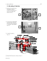
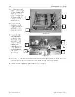
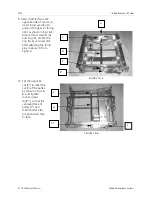
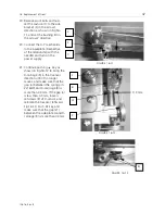
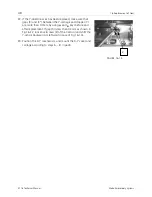
 4. Fix the wire (G) being 

wound on pulley (H) 
securely by using grip band 
(I) so that wire (G) hooked 
to the wire pulley (F) to be 
replaced is not loosened 
from the the pulley (H) as 
shown in Fig.13-3,4.

FIGURE 13-1

B

A

FIGURE 13-2

D

E

FIGURE 13-3

C

H

G

Summary of Contents for EP 1B

Page 1: ...Technical Manual for the EP 1B embroidery machine Part Number 12616 Revision B Single Head Single Needle Easy To Operate Low Power Consumption High Quality Results ...

Page 2: ...out prior written approval of Melco Embroidery Systems Melco reserves the right to revise this publication and to make changes in it at any time without obligation of Melco to notify any person or organization of such revisions or changes All precautions have been taken to avoid errors or misrepresentations of facts equipment or products However Melco Embroidery Systems does not assume any liabili...

Page 3: ...isplay Tube VFD 18 7 Replacement of Power Supply Switch Inlet and Connector Fixing Plate 20 8 Replacement of X Y Mechanism 21 9 Removal of Machine 23 10 Replacement of Thread Breakage Sensor S Board unit Upper Shaft Sensor and Solenoid 24 11 Mounting of Machine 29 12 Adjustment of Bobbin Thread Sensor Solenoid and Thread Breakage Sensor 30 13 Replacement of Wire pulley 33 14 Replacement of X Y Car...

Page 4: ...Table of Contents 12616 Rev B II Melco Embroidery Systems ...

Page 5: ...or the like below the machine as shown in Fig 1 1 1 2 2 Set the machine by adjusting the height of the arm by using a hard book or the like so that baseplate A is almost perpendicular to the floor as shown in Fig 1 1 1 2 Parts marked as shown in in photos show that these parts are to be detached FIGURE 1 1 A FIGURE 1 2 ...

Page 6: ...late adjustment of a play of the lower shaft gear adjustment of needle hook timing relationship depth of needle penetration and lower shaft thrust play and other instructions 1 Remove the needle by loosening needle setscrew A and remove the throat plate by removing setscrew B as shown in Fig 2 1 2 Remove bottom plate D by removing 14 bind screws 4x5 C Fig 2 2 FIGURE 2 1 A B FIGURE 2 2 D C ...

Page 7: ... 4 Set the needle bar to the lowest position and loosen the clamp screw at the bed rubber stopper F position 5 After removing the Hook race body cover by removing bind screws 4x6 5 E remove the bed cover unit H by removing two bind screws 4x12 G Fig 2 4 1 2 4 2 F FIGURE 2 3 E FIGURE 2 4 1 ...

Page 8: ...ap and bobbin thread sensor 7 After removing the hook race body cover and hook body turn the lower shaft gear in the arrow 1 direction as shown in Fig 2 6 loosen socket screw K and shift the lower shaft gear rightward in the arrow 2 direction Loosen socket screw L next 8 Loosen socket screw M shown in Fig 2 7 J FIGURE 2 5 K L 2 1 FIGURE 2 6 M FIGURE 2 7 ...

Page 9: ...y as shown in Fig 2 9 mount the needle and set the needle bar to the lowest position Set the hook body tip to the rear side of the needle adjust the gap between the needle and the hook body tip to 0 0 15mm and tighten socket screw L lightly 11 After mounting the hook race body cover adjust the hook race body unit by turning it so that the needle is positioned at the center of the groove of the hoo...

Page 10: ... hook body due to the deformation of the arm 12 Set the part Q of the hook race body unit and hook body tip R to the phase shown in Fig 2 12 approximately 13 After fixing the hook body turn the lower shaft gear in the arrow 1 direction until it touches the wall as shown in Fig 2 13 and lightly press it to the hook shaft gear by shifting it in the arrow 2 direction Turn the lower shaft front bushin...

Page 11: ... needle as shown in Fig 2 14 2 S Shift the hook body by turning it clockwise from its extreme left point by using the hook shaft gear Tighten two screws L Adjust the depth of needle penetration by loosening needle bar clamp screw U Fig 2 14 3 so that the distance between the outer circumference of the hook body and the upper end of the needle becomes 2 3mm in this set phase FIGURE 2 14 1 S FIGURE ...

Page 12: ...ay exists in the hook shaft loosen two socket screws V of the hook shaft ring and tighten the hook shaft by the hook shaft ring while holding the hook driver by hand so as to eliminate the thrust play as shown in Fig 2 16 16 Fix the gearbox rear cap and the bobbin thread sensor by two setscrews J In this case press the bobbin thread sensor to the hook race body unit shown by an arrow as shown in F...

Page 13: ...ight adjustment and other work in addition to the replacement of needle bar unit 1 Remove the top cover unit 2 Remove setscrew A two setscrews B and snap ring C and then remove front bracket D 3 Remove left hand setscrew E shown in Fig 3 2 1 loosen socket screw about 6 turns and then loosen socket screw G Fig 3 2 2 FIGURE 3 1 B A D C B FIGURE 3 2 1 E ...

Page 14: ...2 5 Set guide bar I to the arm in the arrow direction while inserting needle bar crank rod K to the needle bar crank pin as shown in Fig 3 4 3 5 Set guide bar bushing H in the direction of socket screw F of the horizontal hole as shown by arrow so that socket setscrew F meets the horizontal hole of guide bar bushing H and press needle bar supporter J in the arrow direction FIGURE 3 2 2 I G F 2 FIG...

Page 15: ...shown in Fig 3 6 adjust the needle bar supporter J horizontally so that the horizontal gap becomes more then 0 6mm tighten socket screw G and then securely tighten socket screw F 8 Fix front bracket D by setscrews A B while hooking the tip of the thread tension release plate 1 M to the protrusion of disk presser N as shown in Fig 3 7 FIGURE 3 5 K F FIGURE 3 6 G L J FIGURE 3 7 N M A D B ...

Page 16: ...thread tension release lever as shown in Fig 3 8 10 Adjust the height of ring O Set the presser foot to the lowest position as shown in Fig 3 8 and adjust the height of ring O so that the gap between the presser foot bottom and the upper face of the throat plate becomes 1 2 2 0mm Fig 3 9 FIGURE 3 8 O C FIGURE 3 9 1 2 2 0 mm ...

Page 17: ...Cover 13 4 Removal of X Y Cover 1 Remove the carriage cover B by removing three bind screws 3x10 A Fig 4 11 2 Remove X guide bar F and carriage unit E by removing two countersunk screws 4x5 D Fig 4 2 FIGURE 4 1 A B FIGURE 4 2 D E F ...

Page 18: ...w direction Fig 4 3 4 Remove four seat holders I by removing twelve bind screws 3x4 H 5 Shift the Y carriage J to the cover removing position Q Fig 4 4 6 Remove bind screw 3x4 and small plain washer K 7 After loosening two bind screws 3x4 and small plain washers C shift cover L in the arrow direction Fig 4 4 FIGURE 4 3 G1 G2 H I FIGURE 4 4 K C L J Q ...

Page 19: ... Rev B 4 Removal of X Y Cover 15 8 Remove bind screw 3x8 and toothed lock washer 3 5 M Fig 4 7 9 Remove ten bind screws 3x4 and finished plain washers 3 N Fig 4 5 6 7 FIGURE 4 5 N FIGURE 4 6 N FIGURE 4 7 M N ...

Page 20: ...cement of A Board LAN Board Power Supply Unit 24V and Power Supply Unit 5V 1 Remove the bottom plate B by removing 14 bind screws 4x5 A Fig 5 1 2 a Replacement of A board C I Remove the connectors Fig 5 3 II Replace A board with a new one by removing fore bind screws 3x6 III Assemble it in the reverse order FIGURE 5 1 A B FIGURE 5 2 D E F C ...

Page 21: ...screws 3x25 III Insert plastic spacer firmly Assemble it in the reverse order c Replacement of the Power supply 24V E and the Power supply 5V F I Remove 2 connectors Fig 5 3 II Replace power supply units with a new one by removing 4 bind screws 3 Confirm the connection of the connectors and assemble the Bottom plate Note When you have replaced the A board or the AT board with a new one please upgr...

Page 22: ...ement of K Board and Display Tube VFD 1 Remove the bottom plate by removing 14 bind screws 2 Remove a connector from the A board 3 Remove the top cover and the belt cover Fig 6 1 4 Remove the front cover by removing 3 bind screws 4x8 A and 1 bind screw4x10 B Fig 6 2 6 3 FIGURE 6 1 FIGURE 6 3 FIGURE 6 2 B A ...

Page 23: ...y tube VFD I Remove the front panel bracket G by removing 2 bind taptight screws 3x8 Fig 6 5 II Remove the shield cover H by removing 4 bind taptight screws 3x16 Fig 6 5 III Replace the display tube after removing the flexible cord from the connector of the display IV Assemble the front cover in the reverse order 6 Assemble the display tube to main body by removing 3 bind screws 4x8 and 1 bind scr...

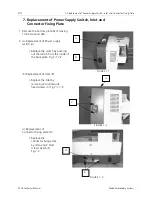
Page 24: ...emoving 14 bind screws 4x5 2 a Replacement of Power supply switch A I Replace the switch by pushing out the switch from the inside of the base plate Fig 7 1 7 2 b Replacement of Inlet B I Replace the inlet by removing 2 countersunk head screws C Fig 7 1 7 2 c Replacement of Connector fixing plate D I Replace the connector fixing plate by removing 2 bind screws 4x6 5 E Fig 7 3 FIGURE 7 1 A B FIGURE...

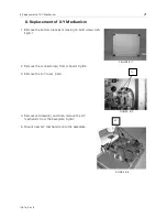
Page 25: ...bottom plate by removing 14 bind screws 4x5 Fig 8 1 2 Remove the connectors A from A board Fig 8 2 3 Remove the X Y cover par 4 4 Remove setscrews B and then remove the X Y mechanism from the baseplate Fig 8 3 5 Mount new X Y mechanism onto the baseplate FIGURE 8 1 FIGURE 8 2 A FIGURE 8 3 B ...

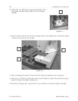
Page 26: ... positioning jig E to the carriage unit The positioning jig is the same as the one for EP1 Fig 8 5 8 After connecting EP 1B and PC start up both of them and initialize the X Y mechanism 9 Adjust the X Y mechanism while moving it so that the needle is inserted into the hole of jig E as shown in Fig 8 5 and tighten setscrews B 10 Remove the carriage unit mount the X Y cover and then mount the carria...

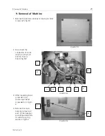
Page 27: ...9 1 2 Disconnect the connectors of cords A B C D E F and G from A board Fig 9 2 3 After loosening bind screw 4x10 H remove pan head screw 6x35 I Fig 9 3 4 Remove the main body by removing 3 each of the hexagon socket head cab bolts J with the spring washers Fig 9 2 FIGURE 9 1 FIGURE 9 2 J G F E D J C B A FIGURE 9 3 H I ...

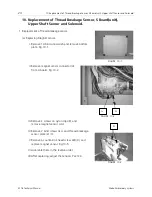
Page 28: ...ing Magnet sensor I Remove 14 bind screws 4x5 and remove bottom plate Fig 10 1 II Remove magnet sensor connector A from A board Fig 10 2 III Remove 2 screws on nylon clips B and remove magnet sensor cord IV Remove 2 bind screws 3x4 and thread breakage sensor plate 2 C V Remove a countersink head screw 2x8 D and replace magnet sensor Fig 10 5 VI Assemble them in the reverse order VII After replacin...

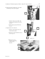
Page 29: ...net I Remove 2 bind screws 4x8 E and replace upper thread tension unit F Fig 10 5 II After replacing adjust the tension Par 12 3 2 Replacement of S board unit I Remove 14 bind screws 4x5 and remove bottom plate II Remove S board connector G from A board Fig 10 2 III Remove set screw 4x6 5 H and remove shuttle cover I Fig 10 6 FIGURE 10 4 F FIGURE 10 5 E D C FIGURE 10 6 H I ...

Page 30: ...ad screws 4x12 J from backside of base plate and remove bed cover K Fig 10 7 V Remove nylon clip SL 3N and clip band and remove 2 pan head screws L and replace S board Fig 10 8 VI After replacing assemble them in the reverse order VII Adjust the sensitivity and tension par 12 1 3 Replacement of Upper Shaft Sensor and Solenoid FIGURE 10 7 J K FIGURE 10 8 L ...

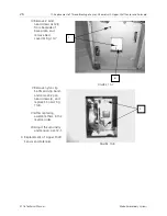
Page 31: ...om the set plate by removing setscrews M and setscrews P shown in Fig 10 9 II Remove snap ring on thread tension release rod N and pull thread tension release rod and plunger of solenoid Then remove spring pin 3x10 O which connect thread tension release rod with plunger and replace the plunger of solenoid Fig 10 10 10 11 FIGURE 10 9 P M FIGURE 10 10 O ...

Page 32: ...kage Sensor S Board unit Upper Shaft Sensor and Solenoid EP 1B Technical Manual Melco Embroidery Systems III After removing set plate by removing screws M replacing the upper shaft sensor by pressing hook of the sensor FIGURE 10 11 N ...

Page 33: ...sing 3 machine mounting screws A and 3 finished plain washers Fig 11 1 2 Fix bind screws 4x5 B after positioning the horizontal position of the machine by pan head screws 6x35 C Fig 11 2 3 Connect connectors Fig 11 3 4 Mount ferrite core K as shown in Fig 11 1 FIGURE 11 1 K A FIGURE 11 2 B C FIGURE 11 3 ...

Page 34: ...nus driver Bobbin wound thread 9 m Bobbin wound thread 15m I Remove dust on the surface of dust sensor and the inside of bobbin thread sensor holder II In case of condenser C2 A is leaning to dust sensor B side lean it to opposite side Fig 12 1 III Mount the S board so that the gap between bobbin thread sensor holder and hook race body cover will be between 0 1 5mm IV Turn handwheel to set the thr...

Page 35: ...ent of the Solenoid Adjust the solenoid with the operation stroke set to be less than 2mm If the solenoid is replaced the thread tension release function must be adjusted I Set the stitch balancing thread tension dial E to 9 Make sure that the thread tension release is secure under the stop condition of the machine If the stitch balancing thread tension dial is functioning loosen setscrew F and fi...

Page 36: ...0mm Front back adjustment II Tighten the screws J so that the gap between sensor and magnet will be 1 0 2 0mm Right left adjustment III Turn on power switch Move the tension spring with finger to confirm that the LED turns on at the thread tension spring on position and turns off at the thread tension spring off position Fig 12 7 IV Confirm that faceplate does not touch the sensor when closed V Co...

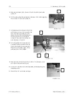
Page 37: ... face of the X Y mechanism Insert a bolt by nut D so that the gear C is free of being scratched when erecting the X Y mechanism as shown in Fig 13 3 Work 1 3 are applicable when removing the X Y mechanism from the baseplate does repair or adjustment 4 Fix the wire G being wound on pulley H securely by using grip band I so that wire G hooked to the wire pulley F to be replaced is not loosened from ...

Page 38: ...pulley F with about 7Kgf by the spring balance in the arrow direction and tighten screws in the order of setscrew K and setscrew J Fig13 5 8 Turn the pulley H clockwise and counterclockwise several times by hand and check the wire tension Draw the wire pulley again if the wire tension is not suitable 9 Remove bolts D and nut E from the X Y mechanism and set cushion B and bushing A 10 Fix the X Y m...

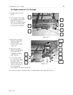
Page 39: ...ng the Y carriage F toward the sensor until it touches stopper G as shown in Fig 14 2 4 Remove setscrews H H and separate the wire I and Y carriage from each other Fig14 2 5 Fix the wires being wound on the pulleys securely by grip bands K so that the right and left wires I are not loosened from pulley J as shown in Fig 14 2 6 Loosen setscrew L and setscrew L and tilt down wire pulley M Fig 14 2 F...

Page 40: ...rs G Fig 14 3 8 Push the X guide bar P slightly downward in the arrow direction as shown in Fig 14 4 9 Draw out Y carriage F in the arrow 1 direction as shown in Fig 14 5 10 Set new Y carriage F to carriage R Set the stitch frame of the carriage to be opposite to the nut side of Y carriage F FIGURE 14 3 N G FIGURE 14 4 P FIGURE 14 5 1 2 Q F Q ...

Page 41: ...n the arrow 2 direction with V bearing Q facing this side as shown in Fig 14 5 14 Apply the wire to right and left wire pulleys M tighten setscrews L L temporarily and cut grip band K which fixes the wire with due care so not to scratch the wire 15 Pull wire pulley M in the arrow direction with about 7 Kgf as shown in Fig 14 7 and tighten setscrews L L 16 Turn right and left pulley J several turns...

Page 42: ...pulley E as shown in Fig 14 9 19 Cut grip band B with due care so as not to scratch the wire Pull the wire pulley E by means of spring balance with about 7Kgf in the arrow direction as shown in Fig 14 9 and tighten setscrew D 20 Turn pulley A clockwise and counterclockwise several times by hand and check the wire C for normal tension If the wire C tension is not suitable pull the wire pulley E aga...

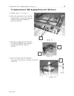
Page 43: ...ving motor cord unit from stepping motor remove the stepping motor by removing setscrews A shown in Fig 15 1 3 Remove the stepping motor from the set plate for stepping motor B after removing setscrew C shown in Fig 15 2 4 Remove the gear from the stepping motor after loosening two setscrews D shown in Fig 15 3 FIGURE 15 1 A FIGURE 15 2 C B FIGURE 15 3 0 8 mm D ...

Page 44: ...tween the stepping motor and the gear as shown in Fig 15 3 Assemble them so that the backlash will be 0 1 0 2mm Fig 15 4 6 Remove 14 bind head screws 4x5 and remove bottom plate Remove Y X motor cord connector and Y X sensor connector E from A board Fig 15 5 7 Pass the removed connectors under the base and remove clip band F Fig 15 6 FIGURE 15 4 FIGURE 15 5 E FIGURE 15 6 F ...

Page 45: ...r connector and 1 bind screw 3x6 G Then replace Y X motor cord unit Y X sensor Fig 15 7 9 Assemble new one in the reverse order 10 Turn on power switch of main unit and PC Keep the condition in which the carriage can be moved Then adjust sensor position par P 69 FIGURE 15 7 G G FIGURE 15 8 ...

Page 46: ...pring pin A shown in Fig 16 1 out of the shaft B and gear C 3 Loosen setscrews D shown in Fig 16 2 and detach the wire H from wire pulley E Remove setscrew G from pulley F and then remove wire holder I Remove wire H from pulley F 4 Remove the opposite wire in the same way as in step 3 5 Loosen setscrews J shown in Fig 16 2 and separate the wire and the X carriage from each other FIGURE 16 1 C A B ...

Page 47: ...r 43 6 Draw pulley F on the sensor L side shown in Fig 16 6 after loosening socket screws K K K screw is a WP screw Fig 16 3 7 Remove ring N by removing setscrew M shown in Fig 16 4 8 Draw out shaft B FIGURE 16 3 K K FIGURE 16 4 M N Q ...

Page 48: ...t as shown in Fig 16 5 Mount thrust washer Q and ring N and fix the ring N by setscrew M after adjusting the thrust play to about 0 1mm Fig16 4 10 Set the opposite cut P to meet the cut P of the pulley as shown in Fig 16 6 and tighten socket screws K K so that the concaved face of pulley F and shaft end face B are positioned face to face FIGURE 16 5 O C B P P FIGURE 16 6 L F B F ...

Page 49: ...holder I by setscrew M 12 Turn wire H counterclockwise by six and half turns on the sensor L side pulley F while closely attaching the wire to pulley F apply it to wire pulleys E in the order of the right and left sides and mount ball R to cut P as shown in Fig 16 8 13 Bring the wire pulley E shown in Fig 16 8 in the arrow direction to eliminate the looseness of the wire and tighten setscrews D li...

Page 50: ...e pulley E 15 Repeat turning the pulleys clockwise and counterclockwise about ten turns by hand 16 Perform steps 7 And 18 in par 13 for both wires to adjust the wire tension 17 After winding the wire H onto pulley F where no X sensor is mounted by 4 turns externally and two turns internally as shown in Fig 16 10 bring the X carriage R to the right Where the Y sensor is not mounted Apply the X carr...

Page 51: ... the power supply 21 Continue pushing key as shown in Fig 16 12 to bring the X carriage R in the Y sensor direction until it no longer moves and make sure that the gap a between the spring pin 2x16 W and X carrriage R is more than 0 3mm If the gap a is less than 0 3mm loosen setscrews B of X sensor and relocate the X sensor leftward Fig 16 13 Push key and make sure that the gap a between the side ...

Page 52: ...he Y carriage and stopper Y are more than 0 3mm by using and keys before and after replacement If gap b is less than 0 3mm as shown in Fig 16 12 loosen setscrews Z of the Y sensor and shift the Y sensor backward or leftward in case of Fig 16 14 23 Position the X Y mechanism and mount the X Y cover and carriage according to steps 5 8 in par 8 FIGURE 16 14 Z ...

Page 53: ...another key to display XXXXX KEY NG and go to the next step In diagnosis mode all keys should function correctly because they are used to examine other parts Otherwise SUMMERY of TEST will be displayed and the result of the key diagnosis will be displayed 2 Buzzer diagnosis 1 After the key diagnosis finishes Do You Hear is displayed The buzzer sounds intermittently The sound is first low and gradu...

Page 54: ... the the VELO signal rotate the handwheel rotate one cycle The number will be 410 to 420 Driving motor has 45 slits on the gear in this case moderating ratio is 9 2 Therefore the number equals 414 45slits x moderating ratio 9 2 414 The number varies between 410 and 420 approximately depending on the rotation of the handwheel and shield plate position 2 The two kinds of signal levels are indicated ...

Page 55: ...ng the judgment key the result is displayed When the key is released PUSH UP LEVER will be displayed 8 Diagnosis of the initial setting sensor for the frame driving motor 1 After the spool diagnosis go to the next step 2 Move the frame support backward by hand and confirm the rightmost item on the screen changes to display REAR Ans H H then press key 3 Move the frame support to frontward by hand A...

Page 56: ...e bobbin thread sensor 1 When BOBBIN SENSOR is displayed press the START key If the upper shaft driving motor rotates and the bobbin has thread FULL BOBBIN is displayed 2 Press the STOP key to stop the driving motor After removing the bobbin case press the START key again When the upper shaft driving motor restarts the following message will appear FEW BOBBIN 3 When all steps are confirmed accordi...

Page 57: ...exit from the individual diagnosis for the item in the following steps the same procedure as the above operations are carried out In the individual diagnosis mode when ALT ENTER keys are pressed the machine goes to the display mode for the diagnosis results The results of the diagnosis will be displayed For example if you only want to diagnose initialization sensor press any key so that the result...

Page 58: ...splays the content for 4 words in hexadecimal notation 16 EEPROM data deletion In individual diagnosis there is an item for deleting the EEPROM data Selecting this item you can rewrite all data to FFFFH which is the same as new chip 1 In individual diagnosis mode press the MENU key and select the item to delete EEPROM data CLEAR EEPROM 2 Press the ENTER key INPUT CIPHER 3 Press the keys in this or...

Page 59: ...12616 Rev B 17 Self diagnosis Mode 55 ...

Page 60: ...56 17 Self diagnosis Mode EP 1B Technical Manual Melco Embroidery Systems ...

Reviews: