12616, Rev. B
14. Replacement of X-Y Carriage
37
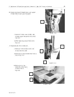
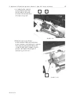
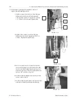
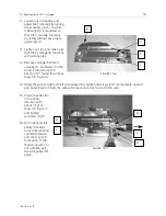
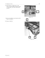
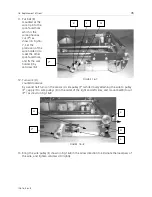
11. Loosen nut (U) slightly, and
adjust the Y-carriage by turning
the eccentric pin (S), to which
V-bearing (Q) is mounted, so
that the Y-carriage functions
smoothly without any play to
guide rails (T).
12. Tighten nut (U), and make sure
that the Y-carriage (F) functions
without any play.
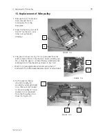
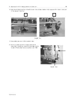
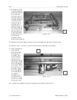
13. Remove carriage (R) from Y-
carriage (F), and insert it in the
arrow 2 direction with V-
bearing (Q*) facing this side as
shown in Fig.14-5.
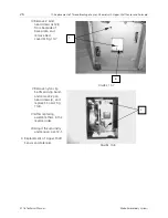
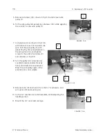
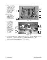
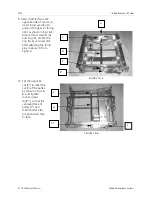
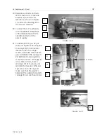
14. Apply the wire to right and left wire pulleys (M), tighten setscrews (L)(L*) temporarily, and cut
grip band (K) which fixes the wire with due care so not to scratch the wire.
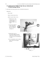
15. Pull wire pulley (M)
in the arrow
direction with
about 7 Kgf as
shown in Fig.14-7,
and tighten
setscrews (L)(L*).
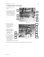
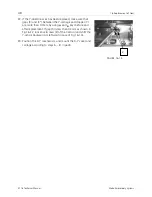
16. Turn right and left
pulley (J) several
turns clockwise and
counterclockwise,
and check wire (I)
for tension. If the
tension of wire (I) is
not suitable, pull
the wire pulley (M)
again.
FIGURE 14-6
T
S
U
R
FIGURE 14-7
M
L
L*
J
K

