MA-5162-ENG
PISTON ADHESIVE MELTER
INSTALLATION
3-3
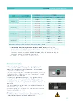
Generally speaking, we can provide as a maximum consumption value 40-50
l/min for a pressure of 6 bar at maximum pump speed.
Other factors
While installing ‘’ series melters/applicators, other practical
considerations should be kept in mind:
• Keep the load opening accessible for comfortable melter/applicator
filling.
• Position the melter/applicator equipment in such a way that you can
easily see the front panel display where temperatures and possible
alarm signals are shown.
• As much as possible, try to avoid unnecessarily long hoses that result
in elevated electrical energy consumption levels and pressure drops.
• Do not install the melter/applicator equipment beside powerful heat or
cooling sources that may have distortional effects upon its operation.
• Avoid melter/applicator vibrations.
• Make sure that the melter/applicator maintenance areas (filter, purging
valve, tank interior, etc.) are easily accessible.
Unpacking
Before proceeding with the installation of the melter/applicator, it should be
removed from its location on a pallet and examined in order to detect any
possible breakage or deterioration. Communicate any defect, even to the outer
packing materials, to your Focke Meler Representative or to the Main Office.
Contents
The ‘’ series packing materials may contain accessories that form
part of the same order. If this is not the case, the following are the standard
components that accompany the melter/applicator:
• Instruction manual.
• Guarantee card.
• Hose couplings.
• Set connectors for Inputs / Outputs.
Mounting the equipment
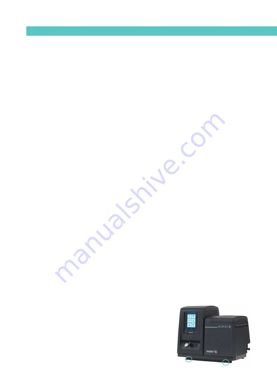
For mounting the ‘’ series set the base in the desired location using
the indicated holes M8 screws.
The ‘’ series equipments have an optional adaptation plate for fixing
‘’ 5, 10, 20, 35 and previous ‘MICRON’ range 4, 8, 16, 32 and ST
machines. To mount the base plate, place it on the machine bench and adjust
its position. Mark and drill the four holes for the base plate’s M8 fastening
screws. The holes may be threaded or non-threaded, depending on the bench
to which they are being attached.
Summary of Contents for Micron + 10
Page 10: ...FOCKE MELER GLUING SOLUTIONS TABLE OF CONTENTS This page is intentionally left blank ...
Page 38: ...FOCKE MELER GLUING SOLUTIONS INSTALLATION 3 16 This page is intentionally left blank ...
Page 74: ...FOCKE MELER GLUING SOLUTIONS 4 36 MELTER OPERATION This page is intentionally left blank ...
Page 84: ...FOCKE MELER GLUING SOLUTIONS 5 10 MAINTENANCE This page is intentionally left blank ...
Page 91: ...MA 5162 ENG MICRON PISTON ADHESIVE MELTER ELECTRICAL DRAWINGS 7 1 7 ELECTRICAL DRAWINGS ...
Page 92: ...FOCKE MELER GLUING SOLUTIONS 7 2 ELECTRICAL DRAWINGS This page is intentionally left blank ...
Page 102: ...FOCKE MELER GLUING SOLUTIONS 8 10 PNEUMATIC DIAGRAM This page is intentionally left blank ...
Page 104: ...FOCKE MELER GLUING SOLUTIONS 9 2 SPARE PARTS LIST This page is intentionally left blank ...

