FOCKE MELER GLUING SOLUTIONS
INSTALLATION
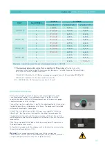
3-8
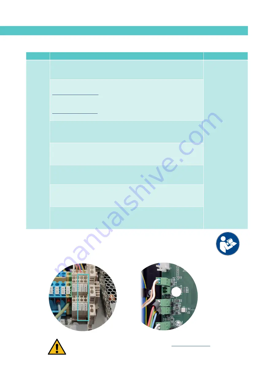
(1) See point ‘4 Use / Settings Menu / Configuration of input and output signals’.
Some outputs will not be shown on the menu, depending on which options are installed in the unit.
(2) Connectors available according to options installed on the equipment.
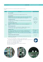
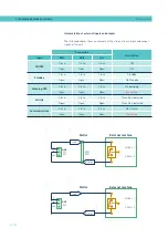
DO2
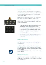
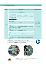
Attention:
The ‘Temperature OK’ output
is not a contact relay
and, as such, it
cannot support voltages of 230 V.
Type
(1)
Description
Terminal/Connector
Output
Standby
Contact indicating that the unit is in STANDBY mode.
Terminal
XDO3.1 / XDO3.2
XDO4.1 / XDO4.2
------
Connector on
HMI card
(2)
DO2
Zones Temperature OK
During the heating phase: contact that indicates that all of the system’s
temperatures have reached a level that is 3°C below its set point value (and the
delay time has elapsed).
During normal operation: indicates that the actual temperature value is neither
below nor above the programmed alarm values.
Machine Ready
Contact indicating that the unit is in READY mode (zones with Temperature OK
and no errors).
Running
Contact indicating that the unit is in RUNNING mode (zones with Temperature
OK, no errors, and pumping activated).
Alarm
Contact indicating that the unit is in ALARM or ERROR mode.
Level
Contact indicating that the adhesive level in the tank has reached the maximum
limit.
No Level
Contact indicating that the adhesive level in the tank has reached the minimum
limit.
Summary of Contents for Micron + 10
Page 10: ...FOCKE MELER GLUING SOLUTIONS TABLE OF CONTENTS This page is intentionally left blank ...
Page 38: ...FOCKE MELER GLUING SOLUTIONS INSTALLATION 3 16 This page is intentionally left blank ...
Page 74: ...FOCKE MELER GLUING SOLUTIONS 4 36 MELTER OPERATION This page is intentionally left blank ...
Page 84: ...FOCKE MELER GLUING SOLUTIONS 5 10 MAINTENANCE This page is intentionally left blank ...
Page 91: ...MA 5162 ENG MICRON PISTON ADHESIVE MELTER ELECTRICAL DRAWINGS 7 1 7 ELECTRICAL DRAWINGS ...
Page 92: ...FOCKE MELER GLUING SOLUTIONS 7 2 ELECTRICAL DRAWINGS This page is intentionally left blank ...
Page 102: ...FOCKE MELER GLUING SOLUTIONS 8 10 PNEUMATIC DIAGRAM This page is intentionally left blank ...
Page 104: ...FOCKE MELER GLUING SOLUTIONS 9 2 SPARE PARTS LIST This page is intentionally left blank ...

