background image

MA-5162-ENG  

 PISTON ADHESIVE MELTER

MELTER OPERATION

4-11

PISTÓN

HMI 

: S02001101 v1.1.2

TC  

: S02200100 v1.0.84

IO FM  : XXXXXXXXX vx.x.x

English

Español

Français

Deutsch

Portugues

Italiano

Česky

Polski

Nederlandse

°F

°C

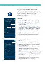
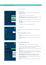
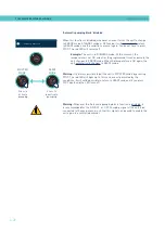
Units and Language

Unit:

English

Units and Lenguage Menu

•  Units:

 To select whether the temperatures are displayed in °C/°F.

• 

Language configuration:  

Press the desired language.

PISTÓN

HMI 

: S02001101 v1.1.2

TC  

: S02200100 v1.0.84

IO FM  : XXXXXXXXX vx.x.x

01

19

2021

17

19

2021-01-19

17:19

HMI 

: S02001101 v1.1.2

TC  

: S02200100 v1.0.84

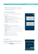
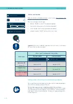
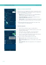
Date & Time

Date

Time

HH

MM

MM

DD

YYYY

Software version

Sensor technology:  PT100

Scan the code to download the user manual

Date and time configuration

This screen allows you to view and modify the date and time data of the 

system.

It also shows:

•  The equipment software version.

•  A QR code, to be able to download the user manual.  

•  The type of technology of the installed sensors.

Summary of Contents for Micron + 10

Page 1: ...ADHESIVE MELTER MICRON PISTON SERIES INSTRUCTIONS MANUAL MA 5162 ENG 190121 GLUING SOLUTIONS HMI v1 1 2 TC v1 0 84 IO FM v1 0 0 ...

Page 2: ... without the express authorization of its owner is strictly prohibited The specifications and information contained in this manual may be modified without prior notice The official language of this manual is only the English language The remaining versions of the manual in other languages are mere translations without any official value or efficacy In case of discrepancies or contradictions betwee...

Page 3: ...s 1 2 Pneumatic components 1 2 Thermal components 1 3 Materials 1 3 Noise emission declaration 1 3 Intended use 1 4 Limited use 1 4 2 INTRODUCTION 2 1 Description 2 2 Modes of operation 2 2 Hot melt melter applicator identification 2 2 Main components 2 3 Control panel components 2 4 Automatic feeder main components optional 2 5 General 2 5 Notes 2 6 MICRON series range 2 6 Incompatibilities 2 7 ...

Page 4: ...3 Unpacking 3 3 Contents 3 3 Mounting the equipment 3 3 Electrical power connection 3 4 Pneumatic connection 3 5 Hose and applicator connection 3 6 Parameter Programming 3 6 External I O connections 3 6 Connecting external inputs and outputs 3 9 Interpretation of external inputs and outputs 3 10 Connecting zone inhibition 3 12 Connecting product passage signal Flowmeter 3 13 Wireless connection Wi...

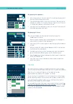
Page 5: ...cteristics 4 5 Navigation icons 4 5 Save changes 4 5 Explanation of the screen contents 4 5 Home display 4 6 General temperature status 4 6 Alarms status 4 7 Calendar status 4 7 Adhesive level status 4 7 Pumping status 4 8 Temperature status 4 8 Temperature and Heating Shortcut displays 4 9 Programming of temperatures 4 10 Programming of statuses 4 10 Calendar 4 10 Units and Lenguage Menu 4 11 Dat...

Page 6: ...4 20 4 Load Menu 4 20 Screen 1 Minimum adhesive level sensor 4 20 Screen 2 Automatic adhesive feeder 4 20 Automatic pumping block function 4 21 Automatic pumping block enabled 4 21 Automatic pumping block disabled 4 22 Off after reset function 4 23 Off after reset enabled 4 23 Off after reset disabled 4 24 Configuration of turning on and activating pumping 4 24 Wireless communication Wi Fi 4 26 Co...

Page 7: ... 5 1 System depressurisation 5 2 Access to pneumatic unit 5 3 Maintenance of the filters 5 3 Changing the pump filter 5 3 Changing the inlet filter 5 4 Cleaning the tank 5 5 Changing adhesive type 5 5 Cleaning burnt adhesive 5 5 Emptying the tank 5 6 Safety Thermostat 5 7 Remove the equipment from its base 5 7 Automatic feeder maintenance 5 8 Cleaning of the unit 5 8 Pneumatic system 5 8 Control o...

Page 8: ...electro pneumatic pressure regulator VP 8 1 Pneumatic connection for 7 cm3 stroke PUMP 8 2 Pneumatic diagram for 7 cm3 stroke PUMP 8 3 Pneumatic connection for 19 cm3 stroke PUMP 8 4 Pneumatic diagram for 19 cm3 stroke PUMP 8 5 Electro pneumatic connection with pressure regulator VP 7 cm3 stroke PUMP 8 6 Electro pneumatic diagram with pressure regulator VP 7 cm3 stroke PUMP 8 7 Electro pneumatic c...

Page 9: ...ASSEMBLY 7cc 9 7 D PNEUMATIC UNIT ASSEMBLY 19cc 9 8 E CHASSIS ASSEMBLY 9 9 F ELECTRONIC ASSEMBLY 9 10 G ELECTRIC ASSEMBLY 9 11 H AUTOMATIC FEEDER FILTER SENSOR ASSEMBLY 9 12 I AUTOMATIC FEEDER SUCTION TUBE 9 13 J AUTOMATIC FEEDER VALVE ASSEMBLY 9 14 EC DECLARATION OF CONFORMITY 10 1 EC DECLARATION OF CONFORMITY Only for equipments with wifi system integrated 10 3 ...

Page 10: ...FOCKE MELER GLUING SOLUTIONS TABLE OF CONTENTS This page is intentionally left blank ...

Page 11: ...perform maintenance on it Also provide necessary safety material appropriate clothing footwear gloves and safety glasses In all cases observe local regulations regarding risk prevention and safety Symbols The symbols used on both the melter applicator equipment and in this manual always represent the type of risk we are exposed to Failure to abide by a warning signal may result in personal injury ...

Page 12: ...voltage Periodically inspect the cables to check for crushing wear and tear as well as to prevent tripping and falls as a result of their placement Although the system meets EMC requirements it is inadvisable to use devices that transmit high levels of radiation i e mobile phones or soldering equipment in their vecinity Hydraulic components As this is a pressurized system precautions related to th...

Page 13: ...eler systems are designed for use with hot melt adhesives They should not be used with any other type of material and especially not with solvents which may cause personal injury or damage to internal system components Some units are specifically designed to use polyurethane reactive PUR hot melt adhesives Using PUR on a unit that is not prepared for that purpose may cause severe damage to the uni...

Page 14: ...bels accompanying the equipment using adequate means of protection during each mode of operation Limited use The equipment should never be used under the following conditions Use with reactive polyurethane or any other material that might cause safety or health risks when heated Use of equipment in environments where cleaning is necessary using water jets Use of equipment to heat or melt food prod...

Page 15: ...The MICRON series includes the 5 10 20 and 35 liter range of hot melt adhesive melters applicators Most of the photographs and illustrations that appear in this manual refer to the 5 liter MICRON melter applicator This model has been used as a reference for writing this manual as its main characteristics with the exception of the tank capacity and the connection outputs are the same as those in th...

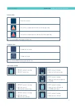
Page 16: ...de Low consumption The melter remains in standby while maintaining all active areas at a programmable temperature The pump remains disabled WARNING Mode The melter detects an incorrect operation or warns the operator about the event The unit can continue to operate ALARM Mode The melter detects an operation error or warns the operator about the event Depending on the type of alarm the unit may con...

Page 17: ...ric pneumatic area 3 Tank access lid 4 Pump air pressure regulator 5 Air pressure gauge 6 Characteristics plate 7 Main switch 8 Hose output distributor up to 6 hydraulic connections 9 Hose applicator electrical connections 10 Compressed air hook up Max 6 bar 11 Set of pump drain valve and filter 11 1 2 11 8 10 9 3 6 4 7 5 ...

Page 18: ...s central leds GREEN YELOW RED 3 RED led pumping OFF 4 STOP RED Button Start Stop Pump 5 Touch screen ON OFF button 6 GREEN led power ON MICRON PISTÓN HMI S02001101 v1 1 2 TC S02200100 v1 0 84 IO FM XXXXXXXXX vx x x 154 154 A 15 35 C 08 31 185 170 1 154 154 2 100 100 3 4 5 42 42 6 B 1 2 3 4 5 6 ...

Page 19: ... 2 Rotary fitting 3 Unload Filter 4 Load Sensor 5 Tank access lid 6 Output air supply to the suction area 7 Electric load valve 8 Input air supply from the grid 9 Junction box 10 Level sensor amplifier 11 Sensor and power supply connector 12 Pneumatic vibrator 13 Suction area 14 Air feeding tube 1 6 4 11 12 13 14 2 3 10 4 7 5 8 9 ...

Page 20: ...VP Prepared Communications _ in blank No communications MB ModBus PB ProfiBus PN ProfiNet EN Ethernet IP W Wifi Pump type _ BP Piston Flowmeter _ in blank Without flowmeter F With flowmeter Light tower _ in blank Not prepared B Prepared Starbi integration _ in blank Not integrated S Starbi integrated 2 channels E Melter Control in blank Internal E Prepared for external control F B Bluetooth _ in b...

Page 21: ...ust be requested separately There is a choice of the low level and colourless white indicator light or the low level and temperature OK indicator light green They are both the same for all machines VP option The VP proportional valve system must be requested separately It is the same for all machines in all cases Incompatibilities 230ºC Float sensor Micron 35 7cc stroke piston pump Micron 35 3 400...

Page 22: ...onal elements can be incorporated Low level of melted adhesive detection system This can be fitted to all the machines in float switch or capacitive sensor options Adaptation plate for previous models For adapting ST machines the previous 4 8 and 16l machines and MICRON range 5 10 20 and 35 liters 4 casters Only for 20 and 35l machines ...

Page 23: ...f according to the location and connections in each particular installation Anchoring screws for the melter applicator equipment Power cord and plug for electrical power Pneumatic pipe and connection to the compressed air system Multicore cable for external electrical control Optionally a gas ventilation system Installation requirements Before installing MICRON series melter applicator equipment w...

Page 24: ...tial switch Consumption figures according to melter applicator and output configuration are included in the table in the section Electrical power connection Compressed air To install MICRON series melters applicators it is necessary to have a dry non lubricated compressed air system with a maximum pressure of 6 bar The applicator s internal pneumatic equipment is able to work with a minimum of 0 5...

Page 25: ...c are easily accessible Unpacking Before proceeding with the installation of the melter applicator it should be removed from its location on a pallet and examined in order to detect any possible breakage or deterioration Communicate any defect even to the outer packing materials to your Focke Meler Representative or to the Main Office Contents The MICRON series packing materials may contain access...

Page 26: ...s required in all cases Consumption figures according to melter applicator and output configuration are included in the table Due to high power connected Focke Meler recommends 3 phases 400 VAC with neutral connection Warning Risk of electrical shock Carelessness may cause injury or death Open the electric cabinet door as far as possible Thread the power cord max Ø18mm through the electrical wall ...

Page 27: ...re gauge can be found pneumatic and hydraulic pressure values the relation between both are 1 13 6 Warning Do not exceed a pneumatic pressure of 6 bars under any circumstances This may cause severe damage to the unit Risk of projection of high speed particles which may cause significant injury 1 The maximum permissible current for a connection is 27 A per phase The table show the maximum current w...

Page 28: ...hose They may be necessary in the future if a hose is removed from its location Perform the electrical hose and applicator connections with the equipment turned off Failing to do so may result in electrical defects in the connection and the appearance of alarm messages on the melter applicator display Parameter Programming Once the melter applicator and its components are installed you will need t...

Page 29: ...tions Modbus Profibus an open contact deactivates them Signals must be enabled in the unit 3 Inhibition of zones Zone inhibition control inputs The unit has 8 contacts to inhibit 8 groups of programmable zones 4 When the contact is closed the respective group is inhibited off when the contact is open the inhibition of that group is disabled activated Temperature Control Board X21 Signals 1 to 4 X9...

Page 30: ...rature OK During the heating phase contact that indicates that all of the system s temperatures have reached a level that is 3 C below its set point value and the delay time has elapsed During normal operation indicates that the actual temperature value is neither below nor above the programmed alarm values Machine Ready Contact indicating that the unit is in READY mode zones with Temperature OK a...

Page 31: ...nterior fitting making sure the cable reaches the corresponding terminals connectors 4 Connect the two cable wires to the corresponding terminal connector The polarity of the connection must be correct 5 Make sure that the cables are properly secured by the terminal s screws 6 Check that the cable is correctly connected and that its passage through the electric cabinet presents no risk of jamming ...

Page 32: ...pen Open OFF Standby Close Close Close Standby Open Open Open No Standby Pumping OFF Close Close Close No pumping Open Open Open No Action Activity Close Close Close Transition detected Open Open Open Transition detected Communications Close Close Close No Comms Open Open Open No action Melter SIGNAL 24V 8 6 1 CLOSE 1 OPEN 0 HMI DI1 DI2 GND IN 24 2 1 3 XDI1 XDI2 2 1 External machine Melter SIGNAL ...

Page 33: ... No Temperature OK Machine Ready 24V Close Close Ready GND Open Open No Ready Running 24V Close Close Pumping GND Open Open Not Pumping Alarm 24V Close Close Alarms GND Open Open No Alarms Level 24V Close Close Level OK GND Open Open Level No OK No Level 24V Close Close Level No OK GND Open Open Level OK 24V OUT 1 2 3 CLOSE 1 OPEN 0 HMI DO3 DO4 2 OUT 1 OUT Melter XDO3 XDO4 2 1 24V OUT 1 2 3 CLOSE ...

Page 34: ... at the rear of the unit and attach it to the interior fitting taking care to ensure that the cable reaches the connectors X21 X9 in the temperature control board 4 Remove the connectors from the board and connect the cable wires to their corresponding terminals To activate it all disabling signals must be switched with the GND pin 5 Reconnect the connectors to the board 6 Check that the cable is ...

Page 35: ...the unit s power 2 Open the front door of the electric cabinet by giving the fastening screw a 1 4 turn 3 Run the signal cable max Ø14 mm through the bushing at the rear of the unit P and attach it to the interior fitting making sure the cable reaches the corresponding terminal X 4 Connect the three cable wires to the corresponding terminal The polarity of the connection must be correct 5 Make sur...

Page 36: ... expense and the possibility to produce turbulences in the hot melt tank with consequent malfunction of the unit Suction tube connection The suction tube should be connected to the swievel elbow of the vacuum feeder inserting it into the inside of the metallic mouth down to its bottom Place the swievel elbow to the most convenient position for installation depending on the location of the hot melt...

Page 37: ... system The Venturi effect applied to the vacuum feeder consists in a decrease of the air pressure by an air flow inside the closed circuit while increasing the air speed when passing through the narrowing of the entry mouth As the entry of aspiration is connected to this point the aspired adhesive stays in it and is transported to the hot melt tank through the flexible communica tion hose Electri...

Page 38: ...FOCKE MELER GLUING SOLUTIONS INSTALLATION 3 16 This page is intentionally left blank ...

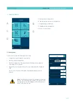
Page 39: ... to number 6 1 Each one has its own set point value The third group is the applicators group It is identified on the front panel depending on the equipment model by number from number 1 2 to number 6 2 Each one has its own set point value The hose and applicator numbers are automatically assigned to the hose applicator channel they are connected to on the rear part of the melter MICRON PISTÓN HMI ...

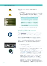
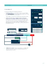
Page 40: ...filled with adhesive and that the operational parameters have been programmed To start 1 Connect the melter s switch When the switch is actuated the GREEN POWER LED remains lit The unit is powered but the screen stays off 2 When you press the ON OFF button the screen lights up and the POWER LED stays lit The main screen shows the unit s status Once it has reached 3 below the programmed temperature...

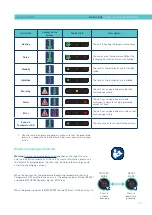
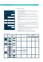
Page 41: ... READY or disabled STOPPED by pressing the STOP key When the pump is deactivated STOPPED the red LED next to the key stays lit Press to activate pumping STOPPED MODE READY MODE Press to deactivate pumping Unit status Symbol on the display Central LED Description Heating The unit is heating the programmed zones Delay 08 31 The zones are at Temperature OK but the Pumping Permission Delay is activate...

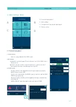
Page 42: ...00100 v1 0 84 IO FM XXXXXXXXX vx x x 01 19 2021 17 19 2021 01 19 17 19 HMI S02001101 v1 1 2 TC S02200100 v1 0 84 Date Time Date Time HH MM MM DD YYYY Software version Sensor technology PT100 Scan the code to download the user manual MICRON PISTÓN HMI S02001101 v1 1 2 TC S02200100 v1 0 84 IO FM XXXXXXXXX vx x x Password Restore password code A 1285 MICRON PISTÓN HMI S02001101 v1 1 2 TC S02200100 v1...

Page 43: ...eters saved MICRON PISTÓN HMI S02001101 v1 1 2 TC S02200100 v1 0 84 IO FM XXXXXXXXX vx x x 30 12 300 P I D 60 C 150 C 152 C PID Standard Standby Temperature Real Set Point T Tank General characteristics In general there are several icons and pieces of information that are repeated throughout the screen navigation so they will be explained at the beginning and then not in the next screens Navigatio...

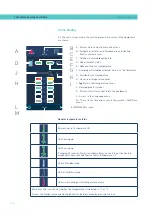
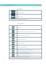
Page 44: ...stem s Date Time menu General temperature status to MAIN MENU screen Active zones in Temperature OK Unit heating up 08 31 Unit heating up Pumping Permission Delay countdown timer once all the active heated components have reached their set point temperature 3 Unit in Standby mode Unit in Inhibition mode Unit in overheating or low temperature alarm Moreover this icon shows whether the temperature i...

Page 45: ...dar not activated Calendar activated Access the CALENDAR menu by pressing the icon WITHOUT automatic loading WITHOUT level sensor WITH automatic loading Adhesive level nearly empty WITH automatic loading Adhesive level nearly empty and LOADING WITHOUT automatic loading WITH level sensor Adhesive level nearly empty WITH automatic loading Adhesive level sufficient and LOADING extra time WITHOUT auto...

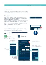
Page 46: ...ting or low temperature warning Note For a zone to be able to give a low temperature warning it must have first reached its set point temperature 170 Zone in overheating or low temperature alarm Note For a zone to be able to give a low temperature warning it must have first reached its set point temperature Access the SHORTCUTS menu by pressing the temperatures area Temperature status Pumping not ...

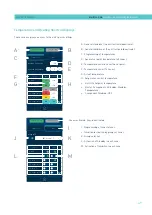
Page 47: ...t Disabled OFF I Programming of zone statuses J Inhibition activation by groups of zones K Group selection L Activation of Standby in each zone M Activation of Inhibition in each zone ON PISTÓN 02001101 v1 1 2 02200100 v1 0 84 XXXXXXXX vx x x Group OFF OFF Group 1 Temperature State Area Standby OFF T Tank D Distributor 1 1 Hose 1 1 2 Applicator 1 2 1 Hose 2 2 2 Applicator 2 General Standby General...

Page 48: ... the Inhibition in all zones With the General Off mode activated Equipment OFF it is not possible to activate each Zone individually 5 To inhibit a group of zones select the group and activate the inhibition green To define the different groups see the Inhibitions point 6 Press Standby in each zone to individually activate green or deactivate white the Standby mode 7 Press OFF in each zone to indi...

Page 49: ...uration Press the desired language MICRON PISTÓN HMI S02001101 v1 1 2 TC S02200100 v1 0 84 IO FM XXXXXXXXX vx x x 01 19 2021 17 19 2021 01 19 17 19 HMI S02001101 v1 1 2 TC S02200100 v1 0 84 Date Time Date Time HH MM MM DD YYYY Software version Sensor technology PT100 Scan the code to download the user manual Date and time configuration This screen allows you to view and modify the date and time da...

Page 50: ...12 Main over temperature applicator 5 2018 05 20 10 03 A66 Thermostat 2018 05 20 09 12 A53 Broken sensorzone hose 6 2018 05 20 08 32 W14 Over temperature applicator 6 RESET ALL RESET RESET RESET Alarms and warnings It displays the alarms and warnings in chronological order It shows 5 alarms on each screen with a total of 3 screens When an alarm warning needs to be reset for the unit to return to o...

Page 51: ... values are directly involved in the heating process Do not modify these values if you do not have the required technical knowledge or without the advice of Meler s After Sales Service MICRON PISTÓN HMI S02001101 v1 1 2 TC S02200100 v1 0 84 IO FM XXXXXXXXX vx x x 30 12 300 P I D 60 C 150 C 152 C PID Standard Standby Temperature Real Set Point T Tank N PISTÓN 01101 v1 1 2 00100 v1 0 84 XXXXX vx x x...

Page 52: ...with external signal External Off Whether it is possible to externally activate or deactivate the inhibition in that group You must indicate which of the seven possible external signals will perform this function One signal can never be enabled in two different groups Selected zones A zone may be selected in more than one group or may not be in any grou 1 2 Sequential Heating This lets you start h...

Page 53: ...3 DO2 XDO3 XDO4 2 3 Input Output Imputs Outputs Standby COMs OFF Pump OFF Temperature OK Alarms Adhesive Level MICRON PISTÓN HMI S02001101 v1 1 2 TC S02200100 v1 0 84 IO FM XXXXXXXXX vx x x XDI1 XDI2 DI3 DO2 XDO3 XDO4 2 3 Input Output Imputs Outputs Standby ON OFF Temperature OK Alarms Adhesive Level Activity MICRON PISTÓN HMI S02001101 v1 1 2 TC S02200100 v1 0 84 IO FM XXXXXXXXX vx x x C1 C2 C3 C...

Page 54: ... activated in each zone If either of those values are reached and maintained for the set time the unit disconnects the heating in the zone causing the error If the error persists 3 minutes later the remainder of the zones are automatically disconnected If the affected zones are the tank or the distributor the unit also stops the pumping Total temperature alarm A temperature C F and a time are defi...

Page 55: ...S02200100 v1 0 84 IO FM XXXXXXXXX vx x x Password Restore password code A 1285 TÓN 154 154 A 15 35 C 08 31 185 170 1 154 154 2 100 100 3 4 5 42 42 6 B 2 1 Password management LOCKED MODE Access is only provided to the HOME screen USER MODE no parameter can be changed There is direct access to the HOME screen and shortcuts by default the user level has no password You can create a user level passwo...

Page 56: ...communication Bluetooth Flowmeter Number of channels Set up the number of electrical outputs enabled in the melter Automatic feeder Activate or disable the operation of the automatic feeder Feeder Activate or disable the operation of the external adhesive feed external liquid load or pellet level Pattern controller Activate or disable the pattern controller functions Level sensor Activate or disab...

Page 57: ...ates the pumping COMM Off Activates or deactivates the communications The outputs can be Standby Indicates that the unit is in Standby mode Zones in Temperature OK Indicates that all active zones are in temperature OK Ready Indicates that the unit is ready to operate with temperature OK and no operating errors Running The unit is pumping with temperature OK and no operating errors Alarm Indicates ...

Page 58: ...e loaded once the lower level sensor has activated tank sufficiently full but not completely full Loading error alarm This defines the maximum amount of time for filling the tank If this time is exceeded the unit displays an alarm Open tank lid alarm An alarm sounds when the tank lid is open and it stops loading immediately Buzzer This lets you set whether or not loading alarms emit a sound TÓN 10...

Page 59: ...does not automatically change to READY mode You must press STOP to disable the pumping block and prepare the unit for pumping Automatic pumping block function The unit has a function for to automatically block pumping due to a voltage drop a direct disconnection from the network or an operating error This function can be activated or disabled via the 2 Extra settings 2 2 Extra settings screen MICR...

Page 60: ...nges to READY mode Warning It is always possible to put the unit in STOPPED mode by pressing STOP The red LED will light up In this case even if permitted by the conditions it will not be possible to return to READY mode until you press STOP again and the LED turns off Warning Whenever the Automatic pumping block function is disabled it is recommended for the ON OFF or OFF Pumping signal of the un...

Page 61: ... unit can be turned on ON through External ON OFF contact if installed and enabled or external communications if installed and enabled or the Calendar function if programmed and enabled or by pressing the ON OFF button on the front screen MICRON PISTÓN HMI S02001101 v1 1 2 TC S02200100 v1 0 84 IO FM XXXXXXXXX vx x x 10 min 85 C 60 s Modbus B 57600 Node 10 2 2 Extra Settings Inside device temperatu...

Page 62: ...et Screen saver Sound on alarm Pumping autolock Configuration of turning on and activating pumping These are different possible pump turn on and activation modes depending on the installation and programming of the unit The following images provide a simplified example of the most typical sequences for turning on and activating the pumping The unit status changes may change by pressing the ON OFF ...

Page 63: ...s Modbus B 57600 Node 10 2 2 Extra Settings Inside device temperature alarm Off after reset Screen saver Sound on alarm Pumping autolock SWITCH ON EQUIPMENT ON STOPPED RUNNIG READY ERROR STANDBY IO FM XXXXXXXXX vx x x 10 min 85 C 60 s Modbus B 57600 Node 10 2 2 Extra Settings Inside device temperature alarm Off after reset Screen saver Sound on alarm Pumping autolock 10 min 85 C 60 s Modbus B 5760...

Page 64: ...status and can schedule unit maintenance or keep a log of all interventions done on it Check with the After Sales Service or your Meler Sales Agent for more information about this service performance Connection configuration 1 Install the Espressif Esptouch app on a smartphone device 2 Connect the device to the local Wi Fi network where you want to connect the melter then run the app 3 On the melt...

Page 65: ...en The unit is programmed for its first use The type of adhesive is changed The working temperature is changed Accuracy losses are noticed Regularly 3 4 weeks for jobs with low adhesive consumption Important During calibration the unit must be at the working pressure and temperature 1 Enter the unit s hydraulic pressure 2 Press Play in Calibration and the unit will automatically do the calculation...

Page 66: ...0 seconds Stop the adhesive application weigh it and enter the value in the Weight section 4 The unit automatically calculates the density and updates the value in the Density section 5 Optionally you can directly enter the adhesive density value at the working temperature manually value between 0 8 and 1 gr cm3 6 Press Save once the process is completed TÓN 70 bar Play st 10h g g cm3 59s Play 7cc...

Page 67: ...hile it is happening To do so press the Play button when you can see that the product has the correct amount of adhesive The unit will then count 10 products take the average consumption per product and indicate it in the target consumption text box Press the save icon to save this number Alarm This is the percentage of the target consumption from which the consumption is considered to be incorrec...

Page 68: ...nt to work with click the white box with the product name The screen will show the 5 selectable products The product you are working with is shown in blue and the product you are now selecting to work with is shown in yellow When you select one of the products its configuration is loaded into the flowmeter with the data previously programmed TÓN Select product Id 01 PRODUCT 1 Id 02 PRODUCT 2 Id 03...

Page 69: ...ve When there are unsaved data the Save option appears in green and you can save by pressing it so as not to lose any data before switching off the unit Each individual product and the total products section can be reset separately MICRON PISTÓN HMI S02001101 v1 1 2 TC S02200100 v1 0 84 IO FM XXXXXXXXX vx x x RESET RESET RESET Flowmeter Statistics TOTAL PRODUCTS Comsuption kg 24 For product g pr 1...

Page 70: ...r calendar programming 3th individual Under Maintenance function key Therefore while the Under Maintenance external signal remains active none of the other three systems can deactivate the function The following criteria are suggested for standby function use If the period of inactivity is less than 2 hours allow the melter applicator equipment to heat as normal If the period of inactivity is more...

Page 71: ...menu to begin the automatic feeding when the low level sensor requests it The automatic loading process is developed according to the following pattern MICRON PISTÓN HMI S02001101 v1 1 2 TC S02200100 v1 0 84 IO FM XXXXXXXXX vx x x 1 s 60 s 90 s 90 s Charge Charge 4 Charge Feeder alarm Sound on alarm Over charge time Charge error alarm Cover opened alarm Automatic charge PLAY 1 Heating 2 Settings 3...

Page 72: ...ing up the system Important Use the working adhesive at the operating temperature Warning Hot zone with high temperatures Risk of burns Use thermal protective equipment 1 With the unit at the operating temperature and the sensor clean fill the tank with the pellets that you are going to work with up to what is considered the tank full level 2 Move the capacitive sensor up down in relation to the t...

Page 73: ...erform the following functions Update the HMI board software Update the IOC board software Update the TC board software Make a complete backup of the system Restore a complete backup of the system Flash memory deletion Make a backup of the Datalogger Warning For more information consult your Focke Meler Representative or the Focke Meler Main Office http www meler eu ...

Page 74: ...FOCKE MELER GLUING SOLUTIONS 4 36 MELTER OPERATION This page is intentionally left blank ...

Page 75: ...eath Clean the exterior using a cloth moistened with water Do not use flammable liquids or solvents To carry out external cleaning Use cleaning products compatible with polyamide materials Apply the cleaning product with a soft cloth Do not use sharp tools or scrapers with sharp edges Operation Frequency Refer to External cleaning Daily Equipment cleaning System depressurization Before performing ...

Page 76: ...m the tank at the same time 7 The tank lid of MICRON 5 and 10 is removed once the tank casing has been dismantled It is simply a matter of sliding the shafts at the ends along the grooves in the casing See diagram 1 The tank lid of MICRON 20 and 35 is removed loosening the side lid screws See diagram 2 8 To assemble the casing follow the instructions in reverse order System depressurisation MICRON...

Page 77: ...ilter performs a first step filtration preventing impurities resulting from burning in the tank and other impurities that may enter from the outside from passing through The filters can be cleaned or replaced with new ones No rule exists for determining when to change the filters Several factors influence this decision the type and purity of the adhesives used the adhesive work temperatures adhesi...

Page 78: ...t this in turn is screwed onto the distributor s adapter via a left handed thread 1 Empty the tank 2 Remove the grid from the bottom of the tank taking care not to scratch it 3 Put the unit on Standby 4 Remove the filter unit with a size 17 socket driver turning the unit s head anticlockwise 5 Depending on how dirty the filter is replace the mesh or the entire unit disposing of it in accordance wi...

Page 79: ...d the adhesive without having used it up as much as possible follow the instructions in the section Emptying the tank 2 Clean the remains of hot melt adhesive on the inside of the tank Warning Use appropriate protective equipment for high temperatures 3 Add the appropriate type and quantity of the new adhesive wait for it to melt and pump at least one full tank through the system hoses and applica...

Page 80: ...passing the adhesive through the pump system In the case of the MICRON 5 the tank does not have a pouring chute so to empty out the adhesive you need to wait until it has cooled and separate it from the walls of the tank making it easier to remove For the other models empty the tank following these indications 1 Keep the tank at working temperature 2 Remove the tank cover and then its casing 3 Low...

Page 81: ... more thorough equipment maintenance it is necessary to remove it from its present location to be able to perform operations more comfortably and with greater accessibility To do this the equipment should be removed from its base following these indications 1 Turn off the machine switch on the door of the electrical cabinet next to the pressure regulator 2 Depressurise the system 3 Disconnect the ...

Page 82: ...um feeder Read carefully in each case the corresponding section If the device does not work or works incorrectly contact the Technical Services meler or Area Representative Cleaning of the unit To maintain the performance of the vacuum feeder in perfect functioning all of its components must be maintained clean and especially the exits in the air suction tube Eliminate waste that can clog the air ...

Page 83: ...is tube should be perfectly free of any glue plugs that impedes the smooth transfer of the adhesive from container to the tank of the melting unit The tube is mostly transparent to facilitate visual inspection of the same Filter maintenance Periodically review the state of the filter located inside the discharge zone Blow compressed air impurities that may have acceded to This filter avoids dust p...

Page 84: ...FOCKE MELER GLUING SOLUTIONS 5 10 MAINTENANCE This page is intentionally left blank ...

Page 85: ...uts 13100 W 6 electrical outputs 6900 W 2 electrical outputs 10500 W 4 electrical outputs 14100 W 6 electrical outputs External functions Inputs Outputs Unit On Off Standby On Off Activity Control Pumping On Off Communications On Off Electrical Outputs Inhibition Standby Zones Temperature OK Machine Ready Running Alarm Level No Level Unit On Off Standby On Off Activity Control Pumping On Off Commu...

Page 86: ...W 6 electrical output 8900 W 2 electrical output 12500 W 4 electrical output 16100 W 6 electrical output External functions Inputs Outputs Unit On Off Standby On Off Activity Control Pumping On Off Communications On Off Electrical Outputs Inhibition Standby Zones Temperature OK Machine Ready Running Alarm Level No Level Unit On Off Standby On Off Activity Control Pumping On Off Communications On O...

Page 87: ...CAL CHARACTERISTICS 6 3 Dimensions micron 5 10 20 435 738 673 627 435 738 673 627 micron 35 587 481 391 341 micron 10 micron 20 587 481 391 341 micron 20 382 341 587 481 391 341 445 micron 10 micron 20 524 878 671 921 587 481 391 435 738 673 627 992 ...

Page 88: ... NAME FECHA DATE TITULO TITLE ESCALA SCALE REFERENCIA REFERENCE SUS A REPLACES CATEGORIA RATE DENOMINACION DENOMINATION HOJA Nº SHEET NUMBER C T B 15 10 2012 1 1 201020170 CHASIS MICRON 20 PISTON 2013 1 de 1 Este plano es propiedad exclusiva de MELER APLICADORES DE HOT MELT S A Todos los derechos reservados This drawing is owned sole of MELER APLICADORES DE HOT MELT S A All rights reserved DPTO OF...

Page 89: ...ment In this case the equipment will be outdated a few centimeters relative to the position of the previous equipment and mooring table To correct this small gap there is an optional adaptation plate to attach the new units of the range in the above position This plate is the same for all units using the holes indicated depending on the unit see dimensions below For the micron 35 units the adaptat...

Page 90: ...FOCKE MELER GLUING SOLUTIONS 6 6 TECHNICAL CHARACTERISTICS This page is intentionally left blank ...

Page 91: ...MA 5162 ENG MICRON PISTON ADHESIVE MELTER ELECTRICAL DRAWINGS 7 1 7 ELECTRICAL DRAWINGS ...

Page 92: ...FOCKE MELER GLUING SOLUTIONS 7 2 ELECTRICAL DRAWINGS This page is intentionally left blank ...

Page 93: ...nder double acting double chamber Ø50x50 7cm3 stroke pump 8 Exhaust port filter 9 Pressure discharge valve 19 cm3 stroke pump 1 Inlet filter filtering disk 2 Pneumatic valve 3 2 80x50 cylinder 3 Pressure regulator 1 8 bar 4 Pressure gauge 0 10 bar 5 Pneumatic valve 5 2 6 Differential valve 7 Pneumatic cylinder double acting double chamber Ø80x50 19cm3 stroke pump 8 Exhaust port filter 9 Pressure d...

Page 94: ... 330500310 2 TUBO POLIURETANO 4 6 1025U0601 1 R 55 3 TUBO Ø6x118 MM 90º ZB 1 330010600 4 INSTRUCCION DE MONTAJE MICRON DENOMINACION DENOMINATION TITULO TITLE Nº DE HOJAS 1 DE 9 FECHA DATE 6 06 07 REFERENCIA REFERENCE IM0004 EDICION NEUMATICA CILINDRO PEQUEÑO 2 INSTALACION NEUMATICA PARA EL GRUPO PEQUEÑO AIR INPUT 6 bar TO PRESSURE DISCHARGE VALVE PRESSURE REGULATOR PRESSURE GAUGE PNEUMATIC UNIT ...

Page 95: ...MA 5162 ENG MICRON PISTON ADHESIVE MELTER PNEUMATIC DIAGRAM 8 3 Pneumatic diagram for 7 cm3 stroke PUMP GRUPO 7cc ...

Page 96: ...4 EDICION NEUMATICA CILINDRO GRANDE 2 Modificaciones Se elimina la válvula de entrada que lleva incorporado el propio grupo y se sustituye por una de mayor tamaño colocada en el exterior La fijación de esta válvula se realiza mediante fijación al tubo de acero de la válvula de descarga INSTALACION NEUMATICA PARA EL GRUPO GRANDE Ø6 R 55 AIR INPUT 6 bar TO PRESSURE DISCHARGE VALVE PRESSURE REGULATOR...

Page 97: ...MA 5162 ENG MICRON PISTON ADHESIVE MELTER PNEUMATIC DIAGRAM 8 5 Pneumatic diagram for 19 cm3 stroke PUMP ...

Page 98: ...re regulator VP 7 cm3 stroke PUMP INSTRUCCION DE MONTAJE DENOMINACION DENOMINATION TITULO TITLE Nº DE HOJAS FECHA DATE 6 06 07 REFERENCIA REFERENCE IM0004 EDICION 2 VP CON GRUPO NEUMATICO 7cc AIR INPUT 6 bar VP VALVE PRESSURE REGULATOR TO PRESSURE DISCHARGE VALVE PRESSURE GAUGE PNEUMATIC UNIT ...

Page 99: ...MA 5162 ENG MICRON PISTON ADHESIVE MELTER PNEUMATIC DIAGRAM 8 7 Electro pneumatic diagram with pressure regulator VP 7 cm3 stroke PUMP 06 03 2012 ...

Page 100: ...OMINACION DENOMINATION TITULO TITLE Nº DE HOJAS 9 DE 9 FECHA DATE 6 06 07 REFERENCIA REFERENCE IM0004 EDICION NEUMATICA MICRON VP 2 VP CON GRUPO NEUMATICO 19cc NOTA PONER REGULADOR DE PRESION EN POSICION DE PRESION MAXIMA MM TUBO NEUMATICO Ø6 R 55 AIR INPUT 6bar TO VP VALVE TO PRESSURE DISCHARGE VALVE VP VALVE PRESSURE GAUGE PNEUMATIC UNIT PRESSURE REGULATOR ...

Page 101: ...MA 5162 ENG MICRON PISTON ADHESIVE MELTER PNEUMATIC DIAGRAM 8 9 Electro pneumatic diagram with pressure regulator VP 19 cm3 stroke PUMP 06 03 212 ...

Page 102: ...FOCKE MELER GLUING SOLUTIONS 8 10 PNEUMATIC DIAGRAM This page is intentionally left blank ...

Page 103: ...arts are grouped together naturally in the same way as they are located in the melters As a visual aid drawings of the parts are included and are numbered to help identify them in the list For further information about the content of the spare parts click on the number of the spare part The lists provide the reference and name of the spare part indicating when necessary whether the reference corre...

Page 104: ...FOCKE MELER GLUING SOLUTIONS 9 2 SPARE PARTS LIST This page is intentionally left blank ...

Page 105: ...ENG MICRON PISTON ADHESIVE MELTER SPARE PARTS LIST 9 3 B H I J Spare parts for automatic feeder E F G B D C A TANK GROUP ELECTRONIC GROUP DISTRIBUTOR GROUP PUMP GROUP PNEUMATIC UNIT ELECTRIC GROUP CHASSIS GROUP ...

Page 106: ...5 5 150113410 Tank insulation mantle micron 5 5 150113420 Tank insulation mantle micron 10 5 150113430 Tank insulation mantle micron 20 5 150114920 Tank insulation mantle micron 35 6 150113440 Insulation mantle inlet tank micron 5 6 150113450 Insulation mantle inlet tank micron 10 6 150113460 Insulation mantle inlet tank micron 20 6 150121370 Insulation mantle inlet tank micron 35 7 10100070 Flat ...

Page 107: ...valve assembly 4 1 150021830 Compensation valve piston plunger assembly 4 2 10100096 Compensation valve spring 4 3 R0009267 Compensation valve shaft bushing 5 150022110 Compensation valve plug with O ring 6 150024750 Depressurisation valve assembly 6 1 150024760 Pressure discharge valve o rings Seal Ø5 6 1 150131300 Pressure discharge valve o rings Seal Ø9 05 7 10100082 Pump plug with o ring 7 1 1...

Page 108: ...3 150113570 Tank pump distributor seating O ring kit 4 150113530 7cc pump guide bushing kit 4 150113540 19cc pump guide bushing kit 5 150020590 Short ball and socket joint for pump shaft activator 6 150113580 Pump holding support 7cc 6 150113590 Pump holding support 19cc 7 150024970 Inlet valve fitting micron pump 7cc 7 150024980 Inlet valve fitting micron pump 19cc 8 150127550 Cylinder magnetic L...

Page 109: ... 150113650 1 4 flat silencer 3 150114480 Pressure gauge 4 10110031 Pressure regulator 5 150113690 Connector kit for 7cc pump unit without VP 6 150020490 Differential valve with o ring 7 150020500 Control valve with o ring 8 150123650 Inlet solenoid valve 24V DC 9 150060130 Solenoid valve connector 10 150020580 O ring kit of pneumatic cylinder 7cc 5 2 1 6 4 8 9 7 10 10 3 ...

Page 110: ...1 Pressure regulator 4 150113850 Connector kit for 19cc pump unit without VP 5 150123660 Solenoid coil 19cc 24V 6 150060040 Solenoid valve connector DIN 43650B 7 150123670 Intake solenoid valve 24V 8 150020490 Differential valve with o ring 9 150020500 Control valve with o ring 10 150023330 Exhaust silencer 11 150023300 O ring kit of pneumatic cylinder 19cc 1 11 11 10 6 5 4 4 4 7 9 8 3 2 ...

Page 111: ... light 2 150130400 Electrical cabinet casing assembly with warning light 3 150122930 Micron 5 tank housing assembly 3 150122940 Micron 10 tank housing assembly 3 150122950 Micron 20 tank housing assembly 3 150122960 Micron 35 tank housing assembly 4 150130410 Micron 5 tank cover assembly 4 150130420 Micron 10 tank cover assembly 4 150130430 Micron 20 tank cover assembly 4 150130440 Micron 35 tank ...

Page 112: ...ts 2 150122990 Temperature control board 6 outputs 3 150114760 Capacitive sensor and amplifier kit 4 R0001938 Solid state relay 40A 5 150125580 Micron wifi communication antenna card kit 6 150126180 Fuse 10A 5x20 electrical outputs 6 150126170 Fuse 10A 6 3x32 distributor 6 150126160 Fuse 16A 6 3x32 tank 7 150127540 I O flowmeter micron control board optional 3 4 1 1 2 5 6 7 ...

Page 113: ...º Ref Description 1 16010003 Female connector 8 pin PT 100 base housing 2 150020720 Female connector 12 pin Ni 120 base housing 3 150130450 Female connector 8 pin NTC base housing 4 150123000 Cable gland Pg 21 black 5 150119190 Cable gland Pg16 black 6 150114470 Main switch 5 4 3 1 6 2 ...

Page 114: ...IONS 9 12 SPARE PARTS LIST H AUTOMATIC FEEDER FILTER SENSOR ASSEMBLY Nº Ref Description 1 150025800 Capacitive level sensor amplifier and probe 2 150025770 Grid filter 20 mesh 3 150025870 Capacitive level sensor o rings 3 2 1 ...

Page 115: ...eeder Ø30 meter 3 150025670 Metal suction tube 4 150025680 Venturi suction tube 5 150025690 Support for suction tube 6 150025700 Fitting 90 3 8 Ø10 quick plug 7 150025710 Pneumatic vibrator vacuum feeder 8 21300000 Silencer 9 150110180 Straight fitting 1 8 Ø4 quick plug 10 150025740 Reduction Ø10 Ø4 quick plug 150025810 Complete suction tube vacuum feeder 10 6 2 7 5 9 8 1 3 4 ...

Page 116: ...IC FEEDER VALVE ASSEMBLY Nº Ref Denominación 1 150025750 Fitting 90 1 4 Ø10 2 150060080 Coil for solenoid valve 24 VDC 10W 3 150060050 Solenoid valve connector 4 150060070 Complete solenoid valve 2 2 24VDC 5W 5 150025790 Fitting 90 3 8 Ø10 quick plug 1 2 3 4 5 1 ...

Page 117: ...ses to contact with surfaces Part 1 Hot surfaces EN ISO 13849 1 2015 Safety of machinery Safety related parts of control systems Part 1 General principles for design EN ISO 14120 2015 Safety of machinery Guards General requirements for the design and construction of fixed and movable guards EN 60204 1 2006 A1 2009 AC 2010 Safety of machinery Electrical equipment of machines Part 1 General requirem...

Page 118: ...This page is intentionally left blank ...

Page 119: ...ards EN 60204 1 2006 A1 2009 AC 2010 Safety of machinery Electrical equipment of machines Part 1 General requirements EN 61000 6 2 2005 AC 2005 Electromagnetic compatibility EMC Part 6 2 Generic standards Immunity for industrial environments EN 61000 6 4 2007 A1 2011 Electromagnetic compatibility EMC Part 6 4 Generic standards Emission standard for industrial environments EN 50581 2012 Technical d...

Page 120: ...e information speak with your Focke Meler representative Focke Meler Gluing Solutions S A Pol Arazuri Orkoien c B nº3 A E 31170 Arazuri Navarra Spain Phone 34 948 351 110 info meler eu www meler eu Focke Group ...

Reviews: