MAINTENANCE
6-5
MA-5096-E
MV APPLICATOR MANUAL
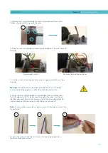
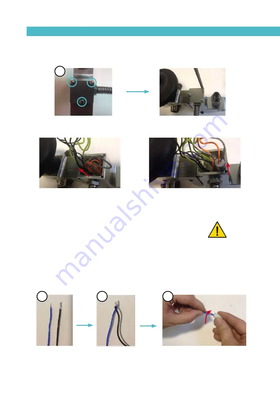
1- Remove the 3 screws fastening the electrical connections cover with a
Philips screwdriver (C) to remove the cover.
2- Slide the sensor or heating resistance gently outwards to remove it from its
housing.
3- Cut the sensor or heating resistance wires at approximately 30 mm from
the end.
Warning: If any difficulties arise when removing the sensor or heating
resistance, heat the applicator a little to facilitate their extraction.
4- Splice the wires of the new sensor or heating resistance with the wires
from the applicator (D). To do this, peel the ends of the wires, twist them
together and insert them in the ceramic cone (E). Once inserted, rotate the
cone clockwise until the wires are firmly in place in the cone (F).
Note: 2 cones will be necessary to replace a sensor or heating resistance (one
for each wire).
5- Insert the sensor or heating resistance in its housing and place the
electrical connections cover.
Removing the sensor
Removing the heating resistance
D
E
F
C
Summary of Contents for MV
Page 1: ...MV APPLICATOR INSTRUCCIONS MANUAL MA 5096 E 020915 GLUING SOLUTIONS ...
Page 8: ...MELER GLUING SOLUTIONS 1 4 SAFETY GUIDELINES This page is intentionally left blank ...
Page 12: ...MELER GLUING SOLUTIONS 2 4 INTRODUCTION This page does not contain any text ...
Page 28: ...MELER GLUING SOLUTIONS 6 6 MAINTENANCE This page does not contain any text ...
Page 32: ...MELER GLUING SOLUTIONS 7 4 SPARE PARTS LIST This page does not contain any text ...


