


USING THE APPLICATOR
4-3
MA-5096-E
MV APPLICATOR MANUAL
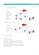
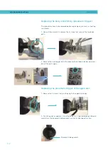
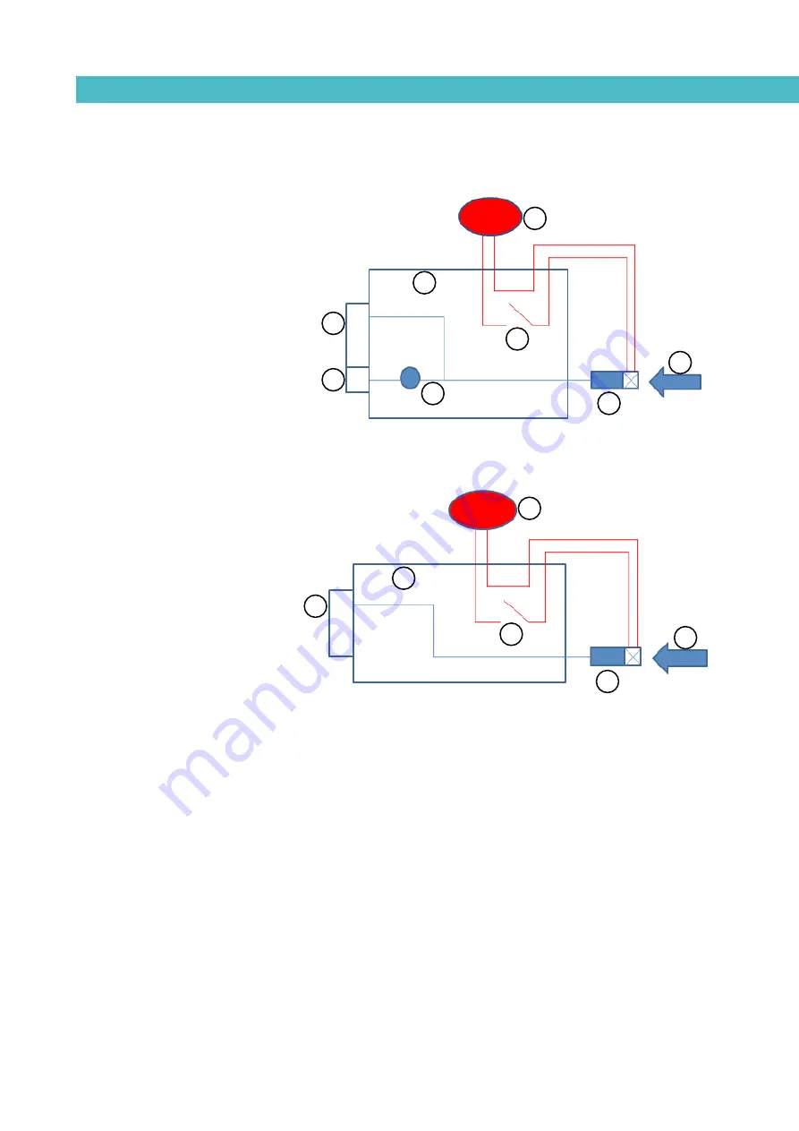
Electric and pneumatic diagrams (swirl version):
Electric and pneumatic diagrams (bead version):
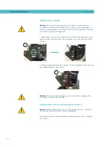
Application adjustments
Adjusting the flow of adhesive
The flow of adhesive needed for application is not adjusted from the MV
applicator, but from the melter unit of the corresponding installation.
If the Meler melter is supplied with a piston pump, the flow is adjusted by the
pressure regulator on the equipment.
If the Meler melter is supplied with a gear pump, the flow can be adjusted two
ways; either by adjusting the motor revolutions (preferably) or by adjusting the
pressure using the bypass valve.
1- Air inlet
2- Electrovalve
3- Electric trigger
4- Electrical power supply
5- Mechanical choke
6- Module
7- Swirl mini-module
8- Applicator body
1- Air inlet
2- Electrovalve
3- Electric trigger
4- Electrical power supply
5- Module
6- Applicator body
4
3
5
6
2
1
4
3
6
7
5
2
1
8
Summary of Contents for MV
Page 1: ...MV APPLICATOR INSTRUCCIONS MANUAL MA 5096 E 020915 GLUING SOLUTIONS ...
Page 8: ...MELER GLUING SOLUTIONS 1 4 SAFETY GUIDELINES This page is intentionally left blank ...
Page 12: ...MELER GLUING SOLUTIONS 2 4 INTRODUCTION This page does not contain any text ...
Page 28: ...MELER GLUING SOLUTIONS 6 6 MAINTENANCE This page does not contain any text ...
Page 32: ...MELER GLUING SOLUTIONS 7 4 SPARE PARTS LIST This page does not contain any text ...


