Rev 1.4
Mellanox Technologies
29
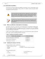
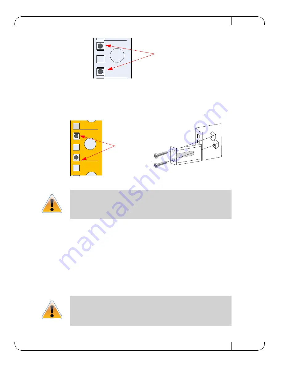
Figure 18: Clipping in the Caged Nuts
5.
Clip 4 more caged nuts into the holes in the rack you will be using to connect the brackets.
Check that both sides of the gateway, power side and connector (IB/ETH) side, are at the
same level in the rack.
6.
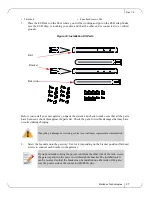
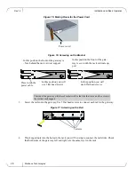
Using two of the bolts for each rail slide, install the rail slides.
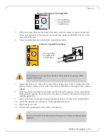
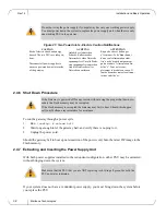
Figure 19: Caged Nut Locations
7.
Tighten the bolts to 9.2 Nm or 81.5 pound inches. If the power cable is on this side of the
gateway, feed the power cable into the slot in the rail slide before screwing it to the vertical
support.
8.
Slide the gateway catching the rail slides into the rails on the gateway. If you extended the
bracket past the gateway to use the slot for the power cord now is the time to put the power
cord through the slot.
9.
Screw in the bolts into the caged nuts and tighten the bolts to 9.2 Nm or 81.5 pound inches.
10.
Ground the gateway. See Section 2.4.3 for grounding instructions.
11.
Plug in the power cord.
12.
You can start connecting all of the cables to the gateway.
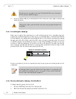
The rail slides are to be installed on the side of the rack where the gateway will be
recessed into the rack.
There is no On-Off switch on the gateway. The gateway will come on when one plug is
plugged in.
The caged nuts
are separated by
a single space
20
20
19
The caged nuts
are separated by
a single space


