Installation and Basic Operation
Rev 1.4
Mellanox Technologies
34
and a cable is plugged into the port with the other end of the connector plugged into a functioning
port). After plugging in a cable, lock the connector using the latching mechanism particular to the
cable vendor. When there is data transfer the light will blink green.
To remove, disengage the locks and slowly pull the connector away from the port receptacle. The
LED indicator will turn off when the cable is unseated.
Care should be taken not to impede the air exhaust flow through the ventilation holes next to the
ports. Cable lengths should be used which allow for routing horizontally around to the side of the
chassis before bending upward or downward in the rack.
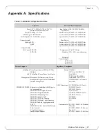
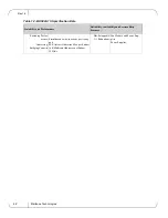
These gateways are able to support direct attached copper cables, optical FC cables, and cables
with media adapters at various lengths and gauges. Check www.mellanox.com => Products =>
Cables for cable recommendations regarding Mellanox approved cables and recommended maxi-
mum cable lengths.
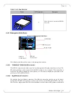
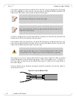
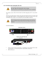
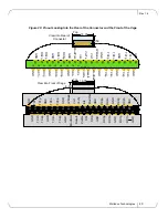
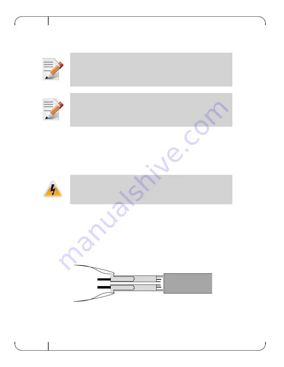
Cables in the bottom row should be inserted up side down in relation to the how the cables are
inserted in the top row.
Figure 23: Top and Bottom Ports
When installing cables make sure that the latch engages.
Always install and remove cables by pushing or pulling the cable and connector in a
straight line with the gateway.
Cables, especially long copper cables, can weigh a substantial amount. Make sure that
the weight of the cable is supported on its own and not hanging from the gateway.


