Rev 1.4
Mellanox Technologies
49
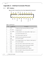
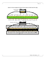
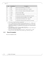
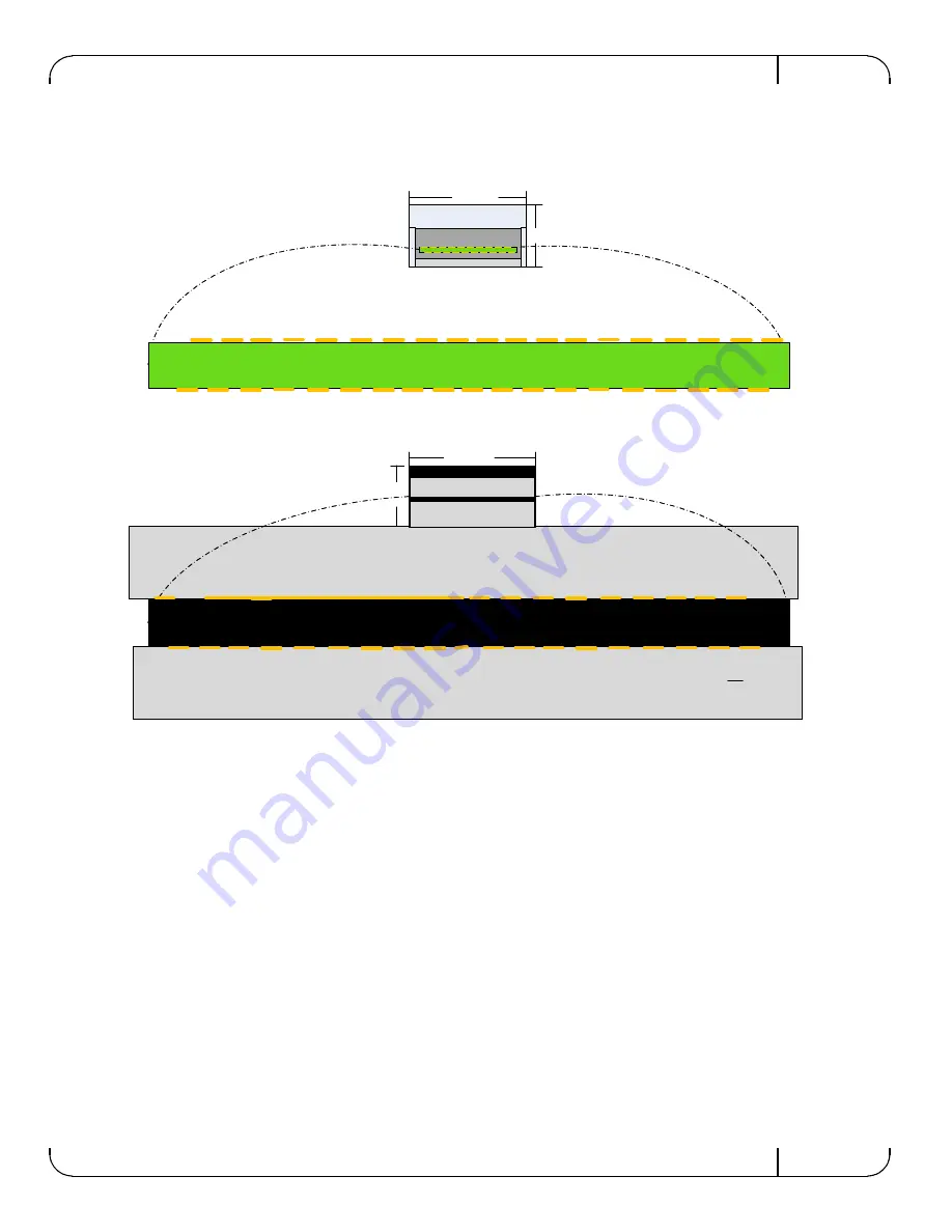
Figure 29: Pinout Looking Into the Rear of the Connector and the Front of the Cage
18.35
8.50
Top
Re
s
e
tL
SD
A
SC
L
ModS
el
L
RX
3
p
TX
2
n
GN
D
Vc
cR
x
1
2
3
4
5
6
7
8
9
1
0
1
2
3
4
5
6
7
8
9
TX
2
p
GN
D
TX
4
n
TX
4
p
GN
D
1
1
1
1
1
1
1
1
1
1
20
GN
D
GN
D
GN
D
RX
3
n
RX
1
p
RX
1
n
30
1
2
3
4
5
6
7
8
9
2
2
2
2
2
2
2
2
2
1
2
3
4
5
6
7
8
3
3
3
3
3
3
3
3
RX
4p
GN
D
GN
D
GN
D
RX
4
n
RX
2
p
RX
2n
TX1
n
GN
D
TX1
p
GN
D
TX3
n
TX3
p
GN
D
Int
L
M
odPr
s
L
Vc
cTx
Vc
c1
LPMode
18.35
8.50
Top
Re
s
e
tL
SD
A
SC
L
ModSel
L
RX
3p
TX2
n
GN
D
VccR
x
1
2
3
4
5
6
7
8
9
1
0
1
2
3
4
5
6
7
8
9
TX2
p
GN
D
TX4
n
TX4
p
GN
D
1
1
1
1
1
1
1
1
1
1
20
GN
D
GN
D
GN
D
RX
3n
RX
1p
RX
1n
30
RX
4p
GN
D
GND
GN
D
RX
4n
RX
2p
RX
2n
TX1
n
GN
D
TX1
p
GN
D
TX3
n
TX3
p
GND
IntL
ModP
rsL
VccT
x
Vc
c1
LPM
ode
1
2
3
4
5
6
7
8
3
3
3
3
3
3
3
3
1
2
3
4
5
6
7
8
9
2
2
2
2
2
2
2
2
2
View into Front of Cage
View into Rear of
Connector

