Rev 1.8
52
Mellanox Technologies
9.3.3 FPGA Load-Flow Debug LEDs
9.4
Board Mechanical Drawing and Dimensions
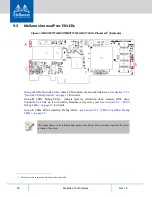
Figure 4: Mechanical Drawing of MNV101511A-BCIT
Table 12 - FPGA Load-Flow Debug LEDs
LED
LED Symbol and Function
Green - power good
Off - power issue
D10 - Power Good
Red - during configuration
Green - when complete
D11- Configuration Done Indication
Red - factory default
Green - user image
D12 - Configuration Image Selection
All dimensions are in millimeters.
All the mechanical tolerances are +/- 0.1mm.
167.65
68.9

