Specifications
Rev 1.8
51
Mellanox Technologies
9.3.1 Network LEDs Operation
Table 10 - Physical and Logical Link Indications
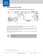
9.3.2 FPGA Debug LEDs
Note:
D2-D9 are the “symbols” of these LEDs as printed on the board.
LED
Function
LED Symbol
Amber - physical link
• Constant on indicates a good physical link
• Blinking indicates a problem with the physical link
• If neither LED is lit, then the physical link has not been
established
D1
Green - logical (data
activity) link
• Constant on indicates a valid logical (data activity) link
without data transfer.
• Blinking indicates a valid logical link with data transfer
• If only the green LED is lit and the Amber LED is off,
then the logical link has not been established
Table 11 - FPGA Debug LEDs
LED Symbols
LED Function
D2
Power Good - Or on all POWER-GOOD inputs. Expected LED ON.
D3
Clock - the LED starts blinking once out of reset and the clock is running.
Expected blinking LED 1Hz.
D4
DDR Calibration DONE - the LED will be ON after power-up, if DDR
calibration is successful.
D5
DDR BIST Passed - DDR Built In Test runs once after power-up. LED will turn
on if test passes successfully.
D6
ConnectX Port Ready - the LED will be ON when FPGA-ConnectX link is up.
D7
ConnectX Port Traffic - the LED will blink when there is FPGA-ConnectX traffic
(TX/SX).
D8
Network Port Ready - the LED will be ON when FPGA-Network link is up.
D9
Network Port Traffic - the LED will blink when there is FPGA-Network traffic
(TX/SX).


