background image


www.mellanox.com 


Mellanox Technologies Confidential 


Dismantling Guide 

OPNs: MIS5600Q-10DNC, MIS5300Q-6DNC,   

MIS5200Q-4DNC, MIS5100Q-3DNC, MSX6536-10R, 

MSX6536-NR, MSX 6518-NR, MSX 6512-NR   

Rev 1.1 


Summary of Contents for MSX6512-NR

Page 1: ...www mellanox com Mellanox Technologies Confidential Dismantling Guide OPNs MIS5600Q 10DNC MIS5300Q 6DNC MIS5200Q 4DNC MIS5100Q 3DNC MSX6536 10R MSX6536 NR MSX 6518 NR MSX 6512 NR Rev 1 1 ...

Page 2: ...NDIRECT SPECIAL EXEMPLARY OR CONSEQUENTIAL DAMAGES OF ANY KIND INCLUDING BUT NOT LIMITED TO PAYMENT FOR PROCUREMENT OF SUBSTITUTE GOODS OR SERVICES LOSS OF USE DATA OR PROFITS OR BUSINESS INTERRUPTION HOWEVER CAUSED AND ON ANY THEORY OF LIABILITY WHETHER IN CONTRACT STRICT LIABILITY OR TORT INCLUDING NEGLIGENCE OR OTHERWISE ARISING IN ANY WAY FROM THE USE OF THE PRODUCT S AND RELATED DOCUMENTATION...

Page 3: ...Board 10 2 5 Extracting the Management Modules 11 2 6 Battery Extraction 12 3 Board Extraction from the Chassis Body 13 List of Figures Figure 1 Front and Rear View of the MIS5600 7 Figure 2 Power Cord Top Bar 7 Figure 3 Power Supply Covers 8 Figure 4 Power Supply Unit 8 Figure 5 Fan Module 9 Figure 6 Leaf Latch 9 Figure 7 Chassis Leaf 10 Figure 8 Ejector Latch 11 Figure 9 Spine Board 11 Figure 10...

Page 4: ...n of meeting the requirements of WEEE recycling Intended Audience This manual is intended for technicians who dismantle the switch systems as a reference for WEEE recyclers Mellanox Technologies emphasizes the importance of carefully following all procedures described in this guide to prevent personal injury Switch OPNs This document is valid for all switch OPNs listed in Table 2 Table 2 Switch OP...

Page 5: ...ely with its suppliers to eliminate hazardous materials from its products There are instances however where it has not proven possible to completely eliminate all hazardous materials Consequently all applicable products are labeled with a crossed out wheelie bin symbol indicating that special care must be applied to their disposal and or recycling Chassis Switch Systems RoHS The chassis switch sys...

Page 6: ...ps screwdriver and a medium slotted screwdriver A screw gun is highly recommended as the larger chassis can have more than 300 screws The pictures displayed in the following pages provide visual guidance explaining how to remove the modules from the mechanical base Chassis switch systems are comprised of Leaf modules located on the front side Spine modules located on the rear side Management modul...

Page 7: ...e left side and even numbered PSUs are on the right side facing the spines There are four Phillips head screws for the cover plates See Figure 3 Power Supply Covers for the location of the PSU covers MGT CONSOLE RST I2C Master L Fans S Fans PSU MGT CONSOLE RST I2C PSU Master L Fans S Fans AC6 AC7 AC8 AC9 AC10 AC1 AC2 AC3 AC4 AC5 1285mm S1 S2 S3 S4 S5 S6 S7 S8 S9 S10 S11 S12 S13 S14 S15 S16 S17 S18...

Page 8: ...latch release while pulling the handle outward 4 Remove all of the PSUs 2 2 Extracting the Fan Units 1 Push and hold the blue latch release 2 Slowly pull out the fan module using the handle 1285mm S1 S2 S3 S4 S5 S6 S7 S8 S9 S10 S11 S12 S13 S14 S15 S16 S17 S18 Mellanox IS5600 IS5600 Mellanox IS5600 IS5600 Mellanox DC AC OK FAIL OK Handle Latch ...

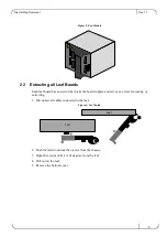
Page 9: ...that locks the board in place and serves as a lever for seating or extracting 1 Disconnect all cables connected to the leaf Figure 6 Leaf Latch 2 Push the latch to unlock the ejector from the chassis 3 Open the ejector until it is 45 degrees from the leaf 4 Pull out on the leaf 5 Remove the bottom cover Leaf Leaf ...

Page 10: ...ewing the 4 slotted screws and remove the heat sink from the board 2 4 Extracting a Spine Board The Spine modules are located on the rear side of the product The Spine module is removed using snap handles 1 Push outward on the latches to unlock the ejectors from the chassis 2 Open the ejectors until they are 45 degrees from the module 3 Pull out on the module using both ejectors Heat sink screws L...

Page 11: ...t sink from the board by unscrewing the 4 slotted screws and remove the heat sink from the board 7 Remove the spine fan module from the spine board 2 5 Extracting the Management Modules 1 Push outward on the latches to unlock the ejectors from the chassis 2 Open the ejectors until they are 45 degrees from the module 3 Pull out on the module using both ejectors Management Module Spine Management Mo...

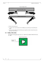
Page 12: ...d remove the board from the casing 6 Remove the heat sink from the board by unscrewing the 4 slotted screws and remove the heat sink from the board 2 6 Battery Extraction In all Mellanox Management boards there is a COIN TYPE LITHIUM BATTERY CR1620 3V 75MA Figure 11 Remove Battery Management Module Spine Management Module Spine Remove the battery ...

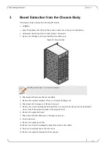
Page 13: ...2 Disconnect all harnesses that are reachable 3 Remove the top fan assembly There are 8 screws holding it on 4 Disconnect the 3 harnesses 1 flat and 2 power 5 Remove the screws holding the fan board there are also latches that need to be unlatched 2 on one side of the chassis and one on the opposite side 6 Remove the upper fan board 7 Disconnect all of the harnesses to the upper power bar 8 Cut al...

Page 14: ... 1 1 Board Extraction from the Chassis Body 14 13 Once the spine framework is removed unscrew the 4 power backplanes 14 Unscrew the Midplane 15 For the 648 port only unscrew and remove the lower fan board ...

Reviews: